Few automotive engineers have had to work so hard for so little credit as those who worked for OEMs in the early 1970s, when they were designing complex systems to lower HC and NOx emissions while fighting to maintain reasonable driveability. One of those fiendishly complex systems was General Motors’ Transmission Controlled Spark System (TCS), and this is how it works.
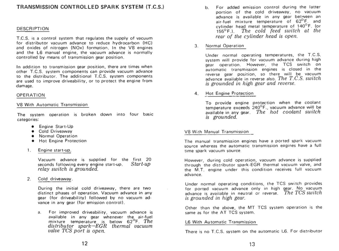
If you think the engineer had it hard, imagine the poor line tech at the average GM dealership. They had to rely on flow charts and tests they’d never seen before to keep these cars patched up and operating as intended. We’ll focus on Pontiac’s 1974 TCS system using Pontiac’s 1974 Exhaust Emissions manual, and we’ll focus on the most complex system, which controls the vacuum advance on V8/automatic cars. The concept behind the system is to limit vacuum advance to high-gear operation most of the time to control exhaust emissions, namely Hydrocarbons (HC) and Oxides of Nitrogen (NOx), and TCS works together with the Exhaust Gas Recirculation (EGR) system (which is outside the scope of this article) to do this. Since more advance raises combustion temperature, producing NOx emissions, the TCS and EGR systems work to lower them while also potentially raising coolant temperatures because, with more retarded timing, the “burn” happens later and can continue as the exhaust valve opens. Retarded timing can reduce HC emissions.
Unfortunately, driveability and temperature control requires the vacuum advance to be operational during engine warmup and when the engine is running hot enough that overheating is inevitable. That adds to the system’s complexity.
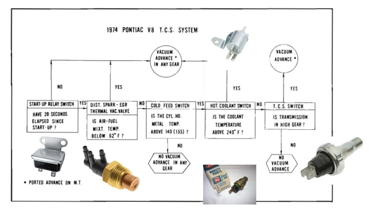
This flowchart shows the main components in the TCS system, which include the following:
- a vacuum solenoid, which is mounted on the intake manifold
- a startup relay switch
- an EGR thermal vacuum valve
- a cold feed switch
- a hot coolant switch
- a TCS high-gear switch
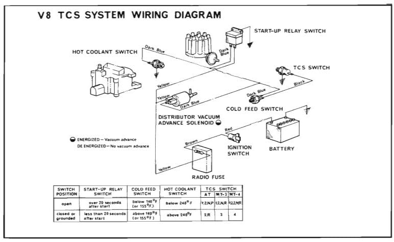
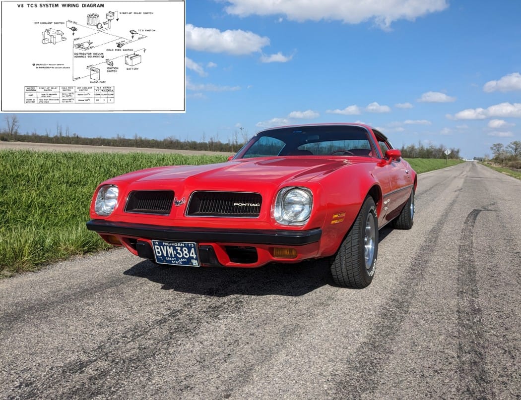
This wiring diagram shows the electrical components of the system and how they are tied together to, in essence, do one thing: limit the vacuum advance system to certain operating parameters.
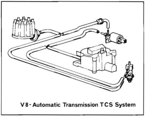
These are the vacuum components in the system, which means that the distributor vacuum advance solenoid, which receives inputs from all other pieces of the system, is the actual piece that switches vacuum advance on and off. Speaking of vacuum advance, automatic cars use full manifold vacuum advance, while manual-transmission cars use ported vacuum advance. The difference is where the carburetor vacuum port is located: Automatic cars are fed vacuum from below the throttle plate, while stick cars are fed vacuum from above the throttle plate.
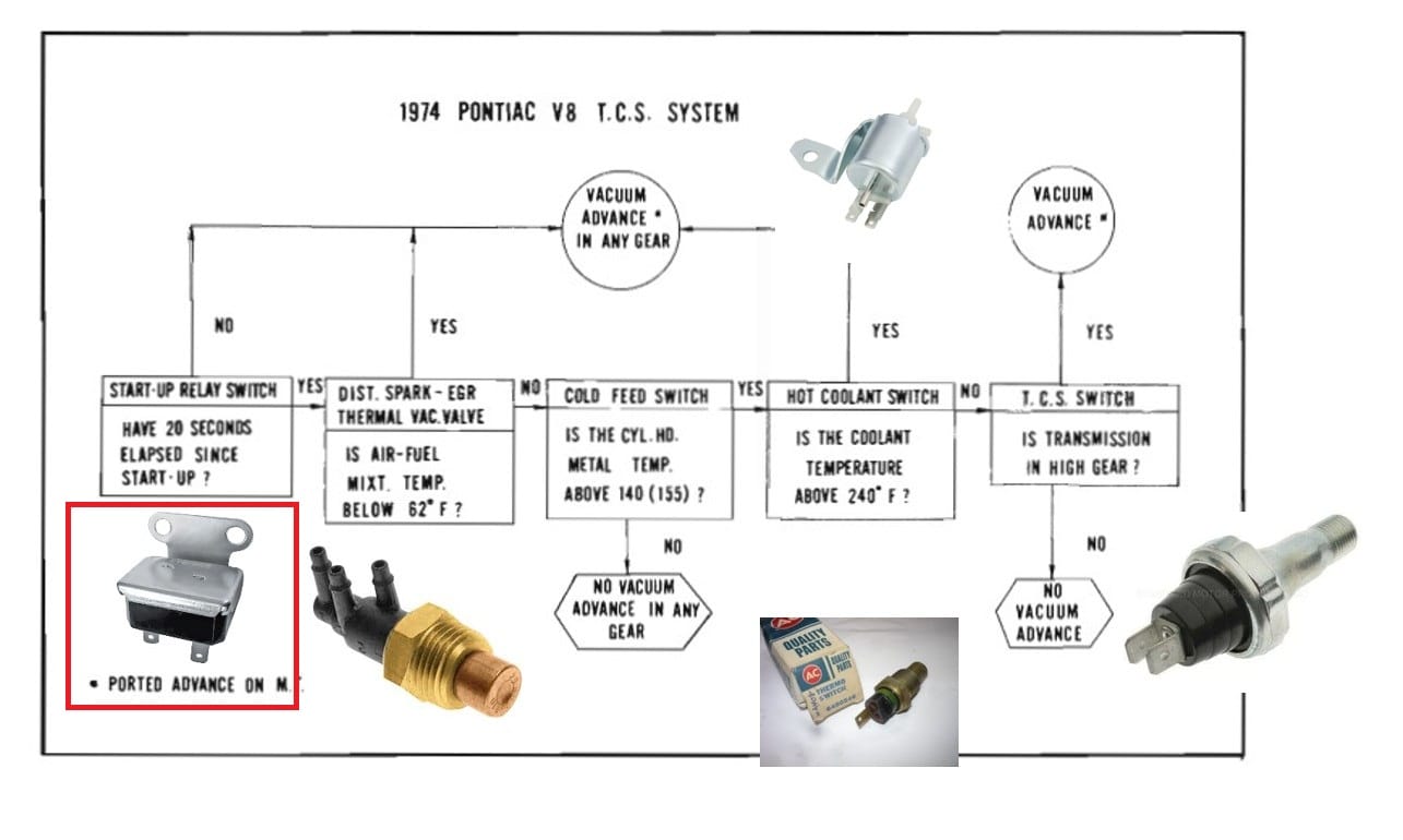
Startup Relay—Engages advance for 20 seconds
Here’s how it all works together. The start-up relay switch is mounted on the firewall, and when the engine starts, the relay is grounded, which feeds voltage for 20 seconds to the distributor vacuum advance solenoid. Therefore, the engine has full vacuum advance in any gear for 20 seconds after the engine starts. The solenoid is fed through a fused circuit from the ignition switch whenever the key is switched on, and that yellow wire is also fed to the start-up relay. A dark blue wire also runs from the relay to the solenoid to complete the circuit. (The relay itself is grounded through its body to the firewall.)
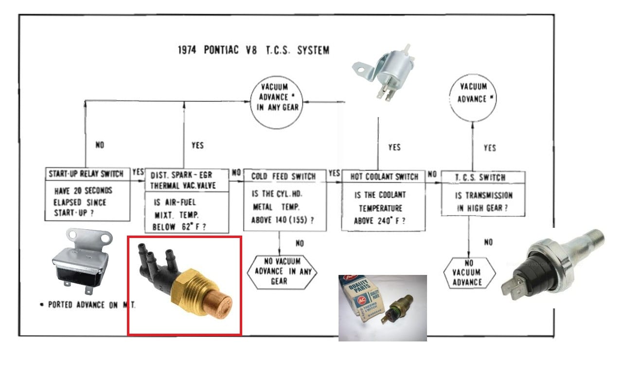
EGR Thermal Vacuum Valve—Engages advance until the air/fuel mixture reaches 62 degrees
Once the relay times out, the car still receives vacuum advance in any gear as long as the “air-fuel mixture temperature” is below 62 degrees Fahrenheit; this is measured by the EGR thermal vacuum valve, which is threaded into the intake manifold. Once 62 degrees is reached, that valve shuts off the vacuum advance in all gears until the cold feed switch, which is mounted to the driver’s side cylinder head, measures between 140 and 155 degrees “metal temperature.” At this point, that switch closes and feeds voltage to the TCS switch, which is threaded into the automatic transmission.
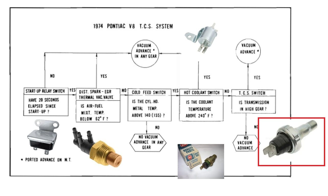
TCS Switch—Engages advance in high gear and reverse
That switch closes to ground, sending a signal to the vacuum advance solenoid on the intake manifold to open and send vacuum to the distributor’s vacuum advance canister. You might wonder how the switch knows the transmission is in high gear; the TCS switch is threaded into the transmission and senses transmission oil pressure, only being fed pressure when the transmission is in high or reverse.
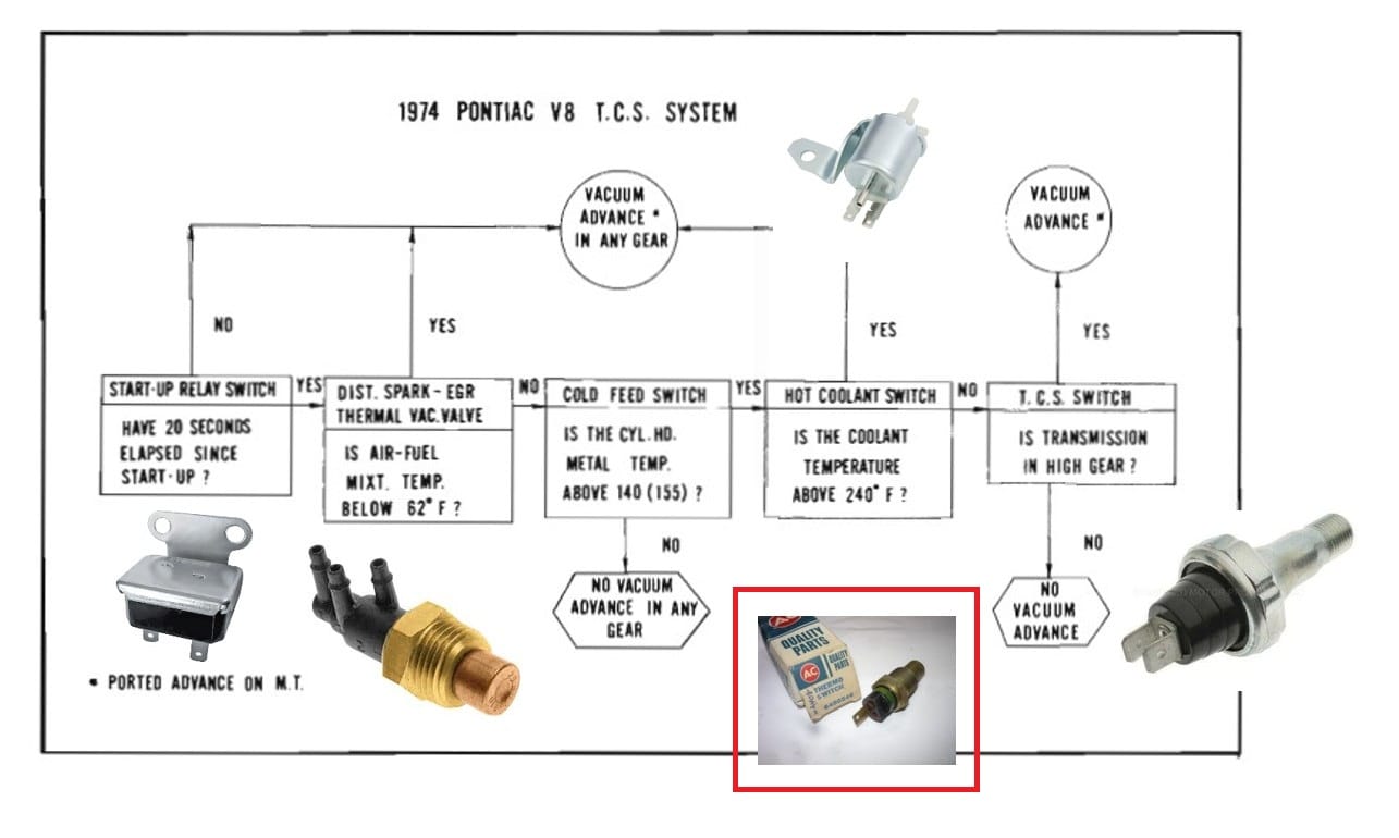
Hot coolant switch—engages advance at 240 degrees to lower engine temps
Once the engine is up to normal operating temperature, the vacuum advance only gets the signal from the solenoid when the driver is cruising down the road at steady-state throttle or backing out of their driveway (which is probably an outcome of transmission oil passage routing rather than a driveability concern). But what happens when the engine starts to get hot in traffic on an automatic-equipped car, which is idling more slowly than a stick car in the same conditions? The hot coolant switch closes to ground at 240 degrees Fahrenheit coolant temperature, sending power through the dark-blue-wired circuit to energize the vacuum solenoid regardless of other conditions, thereby enabling vacuum advance to help cool the engine at idle speed. You might be wondering about that temperature, 240 degrees. At that point, a little extra advance is probably not enough to stave off boil over, which is also why it isn’t uncommon to find an overflow canister under the hood of a 1974 model GM car.
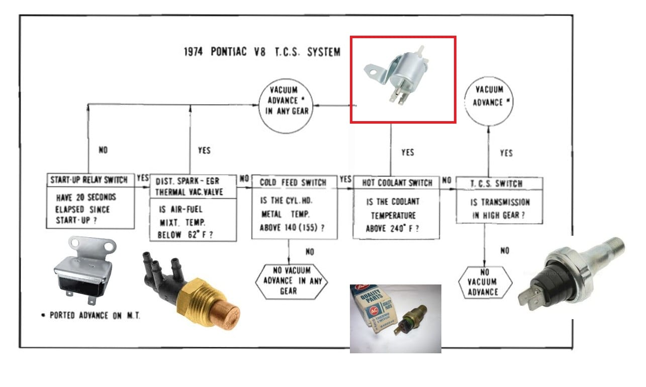
Vacuum Advance Solenoid—The part that ties it all together
And all the inputs, both electrical and vacuum, are fed into this little solenoid that is mounted to the intake manifold with one bolt and one flange. When it is activated by the various circuits (which really come down to “yellow” and “dark blue,” the way things are wired), the solenoid is engaged and allows vacuum to pass from the carburetor to the distributor vacuum advance canister.
All that work and all those pieces were designed so that HC and NOx emissions would stay within required parameters, parameters that were configured through who-knows-how-many miles and hours of testing. While many argue that the OEMs were simply cynical about exhaust emissions and used poor driveability as a means for customers to curse the federal government for requiring cleaner exhaust, I simply marvel at the men and women who had to concoct such complex systems to do what in essence was a simple task. Just think, in these days of cheap microprocessors and sensors, the job could be done with lines of code, but back then, those harried engineers had to do things the hard way. We may not like the outcome, but we have to respect the process.
Related Reading
COAL Capsule/QOTD: Is There An Engineering Decision You Don’t Understand? (1974 Firebird Content) (by me)










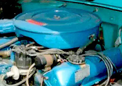



Great write up on a widely misunderstood system. I’ll have to go back and look at my info, I always was under the impression the manifold thermac valve was a water temp sensor (as opposed to intake charge). I have a 1971 Buick 455 Stage 1 car I race in Pure Stock, and in the interest of original appearance I kept all my TCS components on and functional (as shown in the semi finished installation in the pic) But what it takes a sharp eye to see is that I also bypassed the entire system and ran straight manifold vacuum from the carb to the distributor advance unit. The rest is still doing it’s job, but controls no active vacuum path. I also dropped a BB in the charcoal cannister vacuum hose. Sorry, Ozone Layer..
I’ve left the charcoal canister in my Firebird active because it was plugged when I bought the car and it would die at freeway speeds. If I left the gas cap off, it was fine, so the tank wasn’t venting. As I was still learning the car, I decided to keep that system stock and it’s worked fine ever since (about ten years now). In retrospect, I could have just found a vented cap and did what you did.
I’ve said this before, but I’m a dedicated Pure Stock spectator. 🙂 It’s a great event.
Come and see me in the pits! Dont forget this year moved back a week to the 25th/26th.
Depends on the year of the Firebird but my 71 flows just fine with a vented cap. I’d think the vacuum draw would work against you, creating a vacuum where none existed (and magnifying any fuel flow reliance on a neutral state).
Conversely, my 65 Gran Sport has a non vented cap and actually builds pressure with cold to hot ambient temperature change. Pull the cap at the wrong moment and it’ll actually throw a half a pint of fuel at you.. It has a funky early style filler neck and I cant find a vented cap for it..
I have a regular ’65 Skylark hardtop with the non-vented cap. I remember that I filled the tank once on a hot day, and as I started it later on that afternoon, fuel was DUMPING out the vent. Oops!
Do you know why PS was moved back? That seems like a bad move; weather really gets iffy at the end of September.
Good write-up, but not all GM divisions implemented TCS the same. For example, Oldsmobile did not implement the startup or cold driveaway functionality that Pontiac did. The Olds TCS was active at all times (normal operation state) and also incorporated the hot engine protection function through the thermal vacuum switch.
Thank you. I focused on the Pontiac because I own one and covering the differences among all the brands would have been unwieldy. It would be interesting to know why Oldsmobile didn’t need the extra cold-start advance; was it something inherent in the engine where driveability suffered less with less advance when cold (than did the Pontiac’s)?
As an electrical engineer we have datasheets describing the characteristics of electronic components – now these are PDFs but once they were in books. I had a document from Ford describing the function of various emission control components, mostly thermal, electrical and vacuum devices. You really could do a lot with those various parts.
It would be interesting to see how the different manufacturers were dealing with these same requirements. I don’t recall Ford using transmission input to their system, but perhaps they did.
I have a friend who was an EE with Ford just after this period and was involved with Duraspark development. I’ll have to ask him and see what he remembers.
At the time frame when these systems were coming out, I was a partner in a carburetor and ignition shop. I hated the early systems, ervery manufacturer had a different aooroach, GM used the TCS system on most cars, Chrysler went completey with a similar system, Ford had some of each, including a speed sensed system on the 1970 1/2 Falcon I helped the woman I later married buy. That had a small electronic speed sensed if I remember correctly box that the vacuum advance passed through resulting in sluggish light throttle acceleration until you hit the magic speed.
It’s popular to criticize modern cars as “computers on wheels” but these older cars were also. It’s just that they were rolling analog computers, not digital.
Makes me glad my ’66 F100 preceded all of this. keeps it very simple. 🙂
The really great thing about TCS was how easy it was to bypass. The cars ran badly with TCS and it was obviously a stop gap until catalytic converters arrived in 1975.
Looking back, why didn’t Detroit buy fuel injection systems from Bosch or Nippon Denso during the early-to mid 70’s? Or, and maybe less expensively, figure out how to make their carb’d cars run better like the Japanese and some Germans like BMWs of the day?
It was because of Not Invented Here (NIH) syndrome. GM in particular suffered greatly because of it. It was widely know that fuel injection was inevitable by 1975, but the domestic makers couldn’t simply buy a system from Bosch, like the Europeans and Japanese did. No, they had to come up with their own system, but had to flog carbs as long as they could before that. The VW Rabbit had fuel injection in 1978 (from Bosch) but GM had to invent its own system, which was not widely available until 1986.
Territorial license agreements. Bendix controlled a bunch of basic patents for electronic fuel injection, although they were not doing a whole lot with them. They had a cross-licensing agreement with Bosch that did not permit Bosch or its sublicensees (which included Nippondenso and Diesel Kiki) to market electronic fuel injection to U.S. OEMs. (Bosch could and obviously did supply injection to non-U.S. manufacturers for U.S.-market cars, but they could not deal directly with Detroit manufacturers on electronic injection.)
It’s truly amazing. What GM engineers did was to create something I think is properly called an “analog computer”. That is, instead of using electronics to take inputs and use electronic logic circuits to modify outputs, it’s done with switches and solenoids and electricity and vacuum.
It’s a very crude computing device, but it’s really well-done.
Key difference is when it goes awry you can just yank it out, not so much with digital computing in modern cars!
You remind me why I stuck with pre-1972 cars as daily drivers for a long, long time, well into the 80s. Newer stuff (especially 1974+) was so much more complex and, for the most part, didn’t run as well as an older model in a good state of tune. I wonder how many of the dwindling number of 1974 GM cars still running keep this system intact.
I never knew about any of this when my mom had her 74 LeMans. But I knew that my 67 Galaxie with its 390 started easier, ran better, was faster, and got better gas mileage. That 74 Pontiac 350 never ran right during warmup, got awful mileage (like 11 around town) and performance like a slug. Which was too bad, because the rest of the chassis made for a good driver.
Like I have mentioned before, my family was in the garage business. Defeating early emission controls was laughably easy and we did many over the years. There was no emission testing in Victoria BC so nobody was the wiser.
This was no longer necessary when cats were introduced in 1975. GM cars in particular ran much better, especially when cold.
There was a book available from JC Witless (i.e., Whitney) at least through the end of the ’80s, “How to Bypass Your Emission Controls”. I never bought it, and have never found it since then. There are a couple of books by a similar title on the Internet Archive; one for ’73-’77 Ford products and another for ’71-’77 GMs. I guess there wasn’t a Chrysler one, so if you had an AMC, you had to buy the GM and Ford books and get by on roughly 2/3 of the relevant info.
There might have been later editions of these books covering the mid-’70s to early-’80s models.
I immediately bypassed the TCS on my brand new ’72 Nova. In less than a year, I was modifying the engine and threw it all away. One of those modifications was the Rochester fuel injection system from a 1962 Corvette. I don’t know what the emissions were after that but I could tune the mixture until the inside of the tailpipes were almost snow white.
Very interesting read! The 1970 amendments to the Clean Air Act forced carmakers to drastically reduce emissions of several pollutants in a matter of a few years, and there was a real scramble to adopt solutions that in many cases would have benefited from more development time.
Part of me wonders if the reduction targets were not excessively ambitious in terms of timeline; on the other hand, if not forced kicking and screaming, industry would have stalled for eternity any (costly) development
Yes, exactly this. In fact, the U.S. Department of Justice concluded in 1968, after a grand jury investigation whose records are unfortunately now sealed, that the auto industry had engaged in a possibly criminal conspiracy to delay the enactment of earlier emissions standards for as long as possible. The bits of the grand jury evidence that are publicly available are damning: The Automobile Manufacturers Association actively and pretty unequivocally solicited excuses for delaying compliance even on crankcase emission standards.
I was not aware of the investigation, thankyou for your comment – just gave me a new rabbit hole to dive into! This can help explain why the 1970 Amendments strong armed the industry
If you’re curious, you’ll want to read pages 33 to 44 of this document: https://www.congress.gov/92/crecb/1971/05/18/GPO-CRECB-1971-pt12-2-2.pdf
That’s a Justice Department memorandum, released by a member of Congress in 1971. What happened was that the Nixon administration buried the investigation: They mounted a civil rather than criminal antitrust action, and then allowed it to be swiftly settled with a consent agreement where the automakers agreed they would not conspire to obstruct and delay emissions standards, without admitting any wrongdoing. The judge who approved the agreement then ordered all the evidence the federal grand jury had gathered to be permanently sealed. Phil Burton got hold of that memo and introduced it into the record in the House of Representatives. Because the records are sealed, releasing it would have been a crime except for a law that protects members of Congress from being prosecuted for what they say on the record while Congress is in session.
Much appreciated!
Could’ve benefitted from more money and a better attitude, too. There’s a sturdy case to be made that the US auto industry deliberately treated vehicle regulation as a passing fad to be stamped out by whatever means necessary. One of their tactics in that war was to comply with the regulations in the cheapest, nastiest possible ways. Oh, your brand-new car is hard to start, stalls, knocks, hesitates, gets lousy gas mileage, buzzes at you if you don’t fasten the complicated and uncomfortable seat belt, has ugly bumpers? Gee, »tsk« what an awful shame. Not our fault; the government made us do it. Guess you should write to your congressman or something.
They also spent mountains of money, effort, and time fighting the regulations in congress and in the courts of law and public opinion. Which is a pity, because they had massive engineering talent in their employ. If they had put even a fraction of those resources into meeting the goddamn regs instead of making war on them, it would have been to everyone’s benefit.
The malfeasance and shortsightedness was not unilateral; the government really did do some dumb things, like preventing (“anti-trust”) the formation of consortiums to devise good strategies for compliance with the new regs and spread the cost around. I don’t know specifics, but I understand such cooperative efforts were undertaken in Europe and Japan.
There’s more detail on the automaker attitudes (with receipts in the form of links to SAE papers) in my catalytic converter article here on CC.
I had a ’74 Econoline with 302/Automatic. The engine was covered in similar sensors, vacuum lines and valves. Also, it had Duraspark I, California only, 302 only, first year. A previous owner’s mechanic stuck a plug in one of the vacuum lines, undoubtedly to correct some drivability issue. When early emissions checks were just an underhood inspection by a mechanic, no problem. Then, Caifornia set up State inspection centers that ran it on a dyno. Failed CO and HC by a little bit at idle. Shop I hired to fix it was pulling his hair out. He still had to fiddle with mixture a lot just to get it under the limits.
Have you seen an original Honda CVCC car underhood? More miles of vacuum lines.
I don’t see TCS as an analog computer, because all the sensors and switches worked in a binary fashion, applying full vacuum advance or not.
I think it was a rudimentary digital system that made decisions, but didn’t really rise to the level of “computing”.
The HX and HZ Holdens I encounted as an apprentice had a similar system. Possibly identical. Plenty of vacuum lines got re routed, or blocked off with ball from a bearing. I kept balls from bicycle bearings under my work bench for that application.
Disabling EGR and getting full vac advance at any temp and in any gear improved driveabilty big time.
No emission checks in late 1970s Australia, though we were concerned that the cops would defect our own cars for doing the same thing.
As if your average cop would know the hose routing.
Nice work (as usual), Aaron! Though I must pick a nit over your introductory sentence:
My understanding is at that time the relevant engineers at U.S. automakers were designing systems to squeak the cars past their emissions type-approval tests without costing a tenth of a cent more than absolutely necessary. Driveability, fuel economy, and all other concerns were more or less completely out of the question. Among other sources for this belief, I draw on interview responses like this one (Pete Hagenbuch, a Chrysler engineer from ’58ish to ’88ish):
Thanks, Daniel. I was imagining someone like Mr. Hagenbuch testing these cars on the dyno or out at the proving grounds, trying to get that HC number to squeak by. It must have been embarrassing to put all that work in while knowing that the buyer was going to be dissatisfied.
Also worth noting Chrysler used a transmission-controlled system on ’71 and ’72 California cars, to cancel vacuum spark advance unless the transmission was in top gear and certain vehicle speed and engine temperature thresholds were met. Took a giant bite out of driveability; the cars had mushy throttle response at best. Hesitation, stumble, sag, and stalling were common. And that was on the ’71s; the ’72s were much worse because they had EGR with no valve – just an always-open “floor jet” passage directly from the exhaust tract to the intake tract. Maybe you can imagine how poorly those cars ran.
Here’s info on the transmission-controlled NOx control system from the ’71 FSM, cut together to fit in one image: