
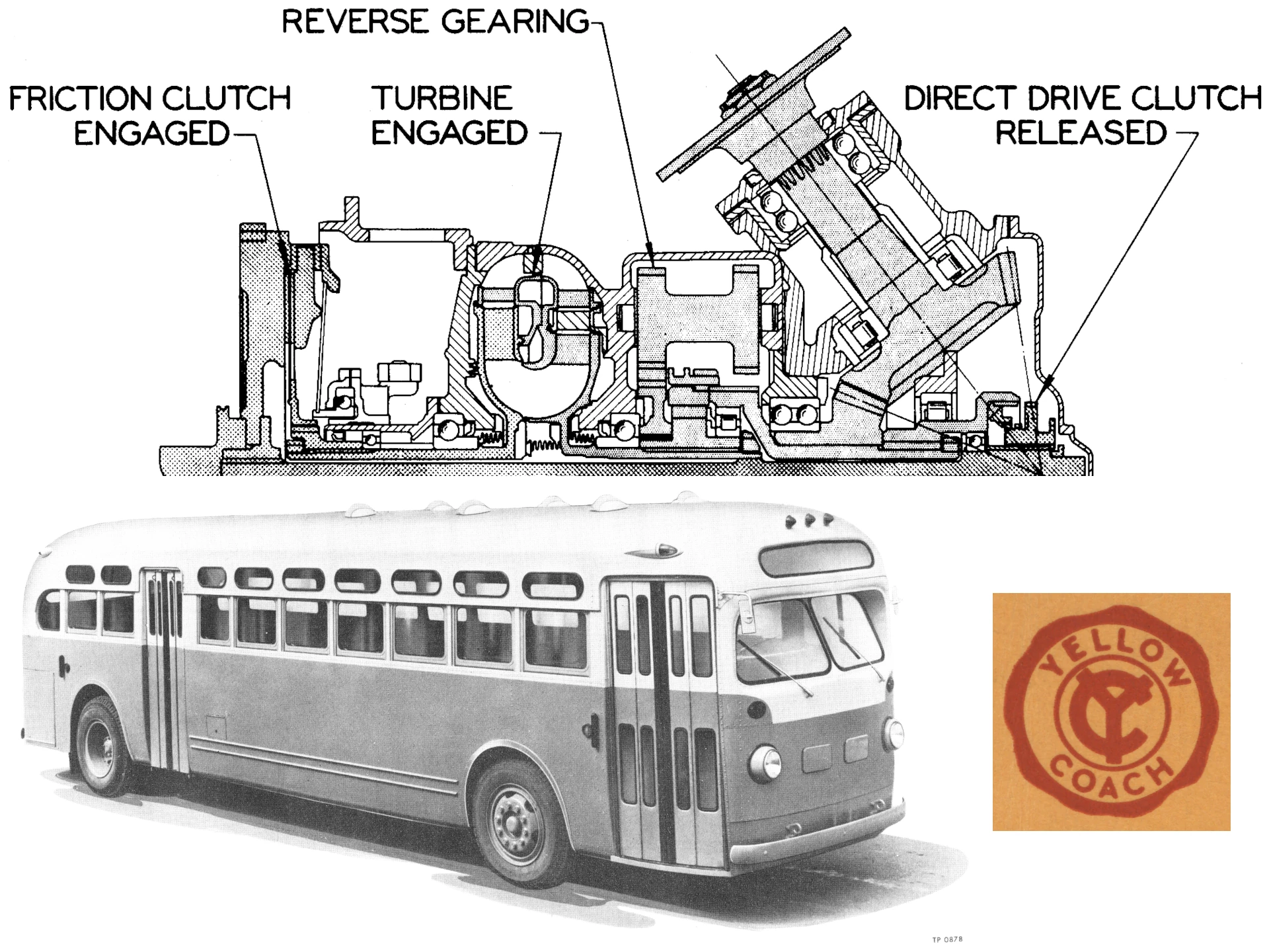
Almost 10 years before Buick’s Dynaflow, the first mass-produced torque converter transmission for passenger cars, GMC transit coaches were already using fully automatic Spicer Model 90 and 91 hydraulic transmissions. Because constant shifting of manual gears in city buses was a chore for the driver, hard on the drivetrain, and made for a jerky ride, these “hydraulic drive” automatics quickly found favor with operators and passengers alike. They were the predecessors of the long-serving GM Allison “V-drive” bus automatic family — continuously variable torque converter transmissions with lockup direct drive clutches, produced into the mid-1970s. Here’s how they came about and how they worked.
Lysholm-Smith Torque Converter
Swedish engineer Alf Lysholm (1893–1973) was an expert in what’s broadly known as “turbomachinery”: As chief engineer of Stockholm’s AB Ljungstroms Angturbin (Ljungstrom Steam Turbine Co.), he received dozens of patents related to air compressors, superchargers, gas turbine engines, and torque converters.
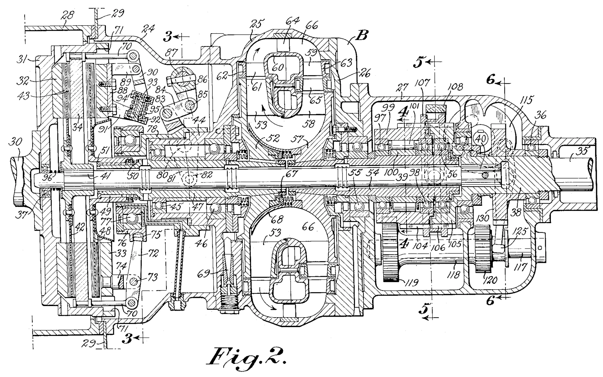
Lysholm didn’t invent the torque converter — German engineer Hermann Föttinger had done that more than 20 years earlier — but in the late 1920s, Lysholm and his colleagues devised and patented a complete torque converter transmission suitable for cars, trucks, or buses, with gears for reverse and a lockup clutch for cruising.
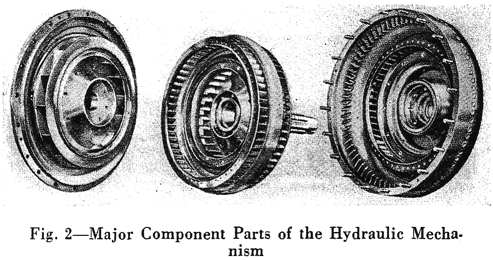
The Lysholm-Smith torque converter, as it was known back then, was quite a bit different than the simpler three-element converters used in later passenger car automatics. It had an engine-driven pump, two sets of turbine blades, and two sets of reaction blades. The reaction blades were permanently attached to the inside of the housing, and unlike the stators in later automotive converters, they were fixed, with no overrunning clutches to let them freewheel when they weren’t needed. Their blade angles were chosen to provide good torque multiplication without excessive shock losses to hurt efficiency. This allowed the Lysholm-Smith to offer a high average torque ratio — peaking at about 5 to 1 at stall — over a broad range of speeds.
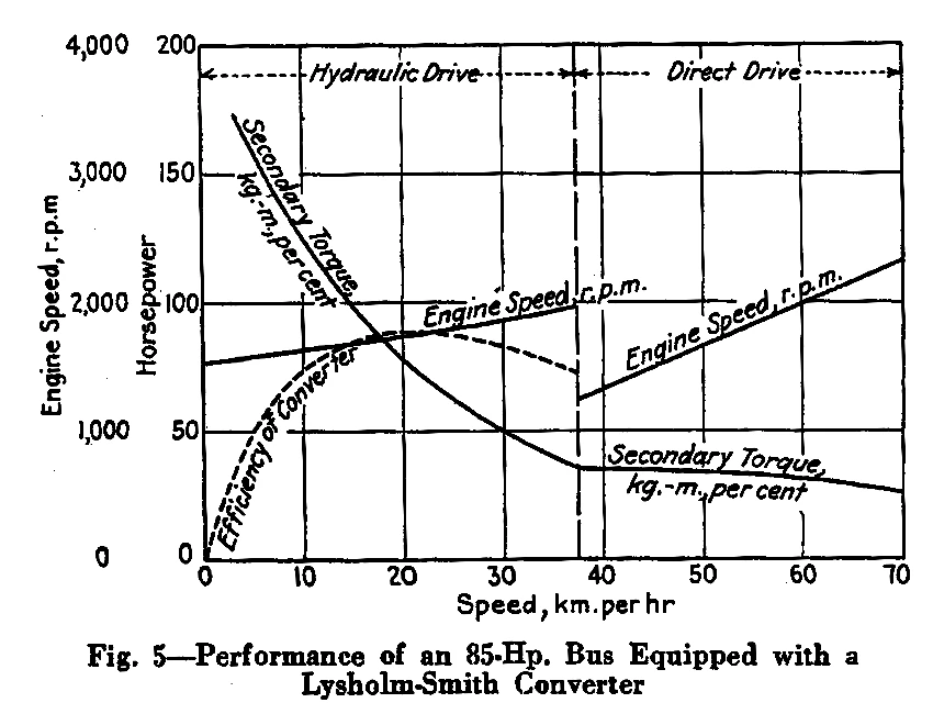
With this type of torque converter, efficiency is good at medium speeds, but drops off at higher speeds because of the fixed blades. To get around that, Lysholm provided a lockup clutch that could be engaged to put the transmission in mechanical direct drive. An overrunning clutch allowed the converter to idle and even stop while the output shaft was being driven by the engine. There was also an additional clutch to disconnect the engine from the converter in neutral. At low speeds, drive was through the torque converter in forward or reverse, with reverse provided by a set of spur gears in a conventional dual-shaft arrangement.
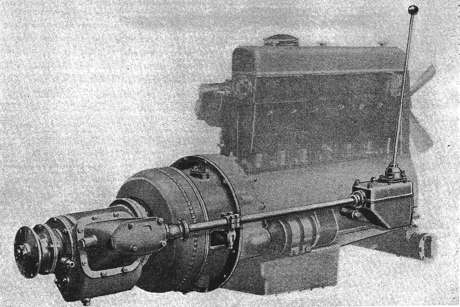
British bus manufacturer Leyland Motors licensed the Lysholm design in 1931 for truck, bus, and railcar applications. Leyland put the torque converter transmission into production in 1933, beginning with its double-decker Titan TD3c buses. On the Leyland hydraulic transmission, the direct drive clutch had to be engaged or disengaged manually with a control lever, so it wasn’t truly automatic (although this could be a plus, since it allowed a stalled bus to be push-started or tow-started). The British journal Commercial Motor described the performance of the transmission like this:
From the city-bus point of view undoubtedly the first point about the performance is the absolutely smooth and unpunctuated acceleration from rest. With the control lever in the forward or torque-converter position the engine idles while the bus remains stationary. The accelerator is depressed and the engine speed quickly rises to its most efficient value, the vehicle gliding forward at a steadily increasing pace and the engine speed being constant.
There is no jerk whatever and passengers can pass in comfort to their seats without being thrown off their balance as they often are when the throttle of a normal bus is eased for each gear change. There is, of course, no gear noise during the indirect-ratio period, and this silence is bound to continue for the life of the vehicle, whereas the ordinary gearbox gets noisier with wear. Further, any roughness in the running of the engine is cushioned out because the power is transmitted hydraulically. This is an important point in connection with the use of oil engines, which, in some cases, do not give such a smooth torque at low speeds as modern petrol engines. The hydraulic drive also damps any propeller-shaft vibration, and, of course, makes for lengthened life of chassis parts.
Between 1933 and 1939, Leyland built about 2,000 of these transmissions for bus use. According to British bus writer Gavin Booth, they were never as popular with British transit companies as standard transmissions or the Wilson preselector, but they gave good service, especially in areas with lots of steep grades.
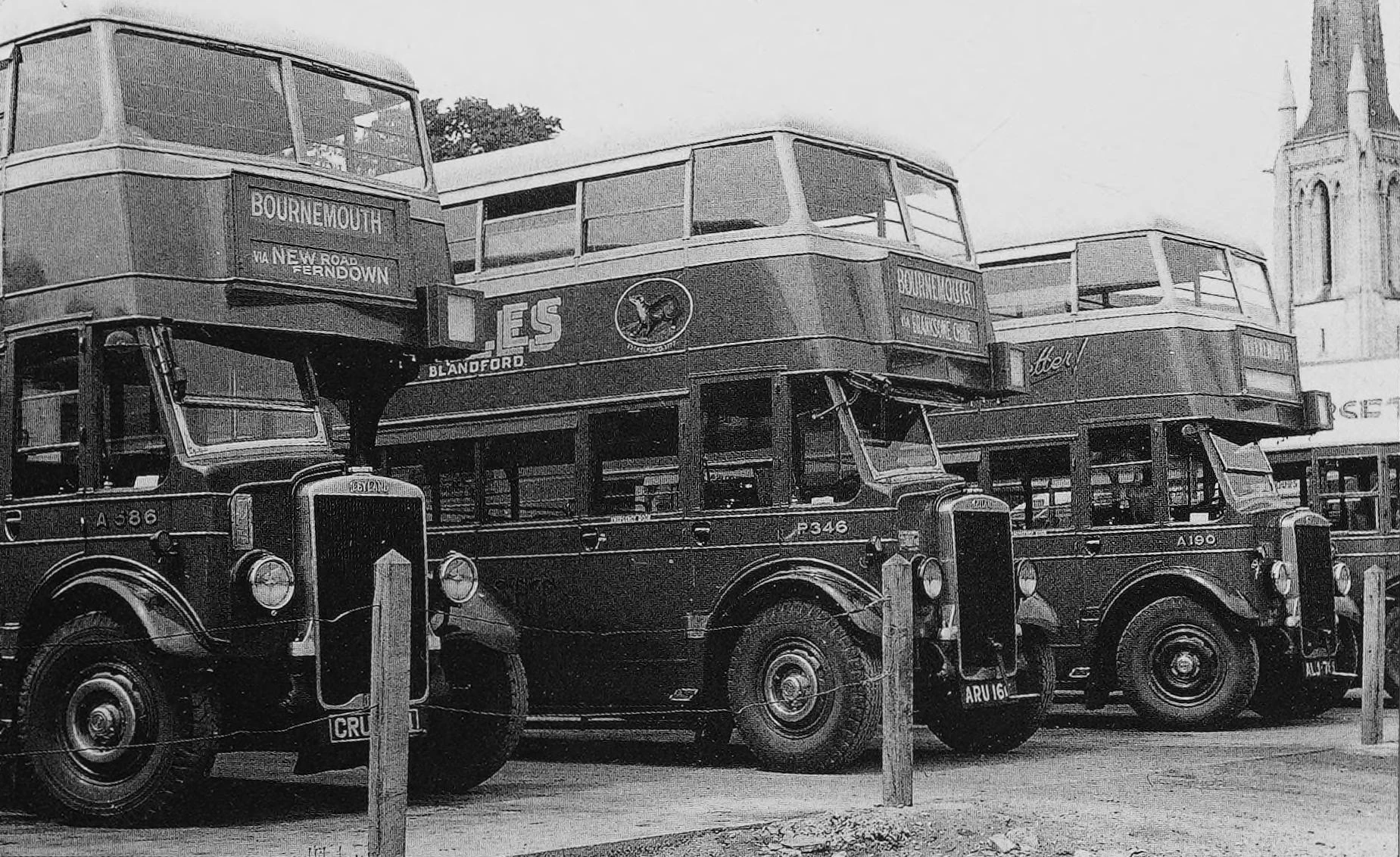
“The users were in all instances enthusiastic,” remarked Yellow Coach engineering VP Col. George A. Green in 1939. “The performance of the transmissions is admirable, and the vehicles equipped with these transmissions are extremely popular with the public.” (Keep in mind that this was years before the adoption of torque converters for passenger car transmissions. The first passenger car with a torque converter, the Invicta Black Prince, wasn’t exhibited until 1946, and the first Buick Dynaflow didn’t arrive until 1948!)
Yellow Truck and Coach (Yellow Coach) and GMC
The history of Yellow Coach and what’s now GMC is a little confusing, requiring some explanation. Yellow Coach was founded in 1923 as a subsidiary of Yellow Cab and reorganized in 1925 as the Yellow Truck and Coach Manufacturing Company. General Motors president Alfred P. Sloan Jr. arranged a deal whereby GM essentially traded the General Motors Truck Corporation and its facilities in Pontiac, Michigan for a controlling interest in the reorganized Yellow Truck and Coach company. Until 1943, therefore, General Motors Truck and Coach was technically a division of Yellow Coach rather than General Motors. In 1943, GM bought out the remaining Yellow Truck and Coach stock, making the company a wholly owned GM subsidiary, and phased out the Yellow Coach name, instead calling the division General Motors Truck and Coach, or GMC, which of course still survives today.
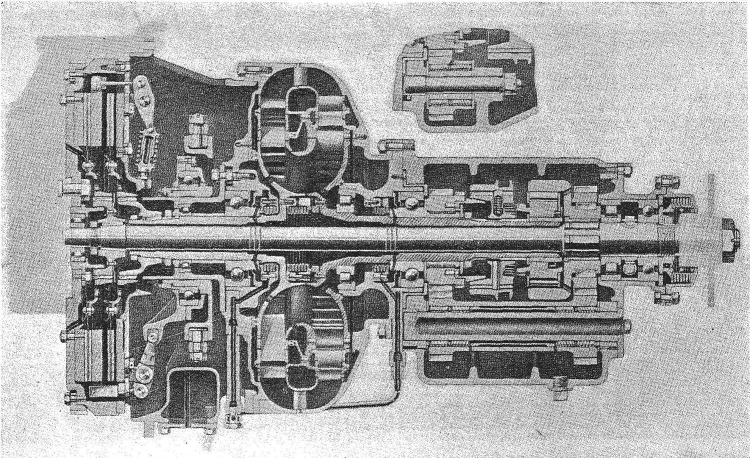
George Green, Yellow’s Australian-born engineering chief, had previously worked in the British bus industry and still had good connections there. Green was well aware of the Leyland hydraulic transmission from when it was first exhibited in 1931, as was the Toledo-based Spicer Manufacturing Co. In fact, in 1933, Spicer obtained one of the earliest production examples of the Leyland transmission for evaluation. Spicer and Yellow Coach were both very interested in hydraulic drive for bus applications, although they agreed that the transmission would need more development to suit American bus engines and driving conditions.
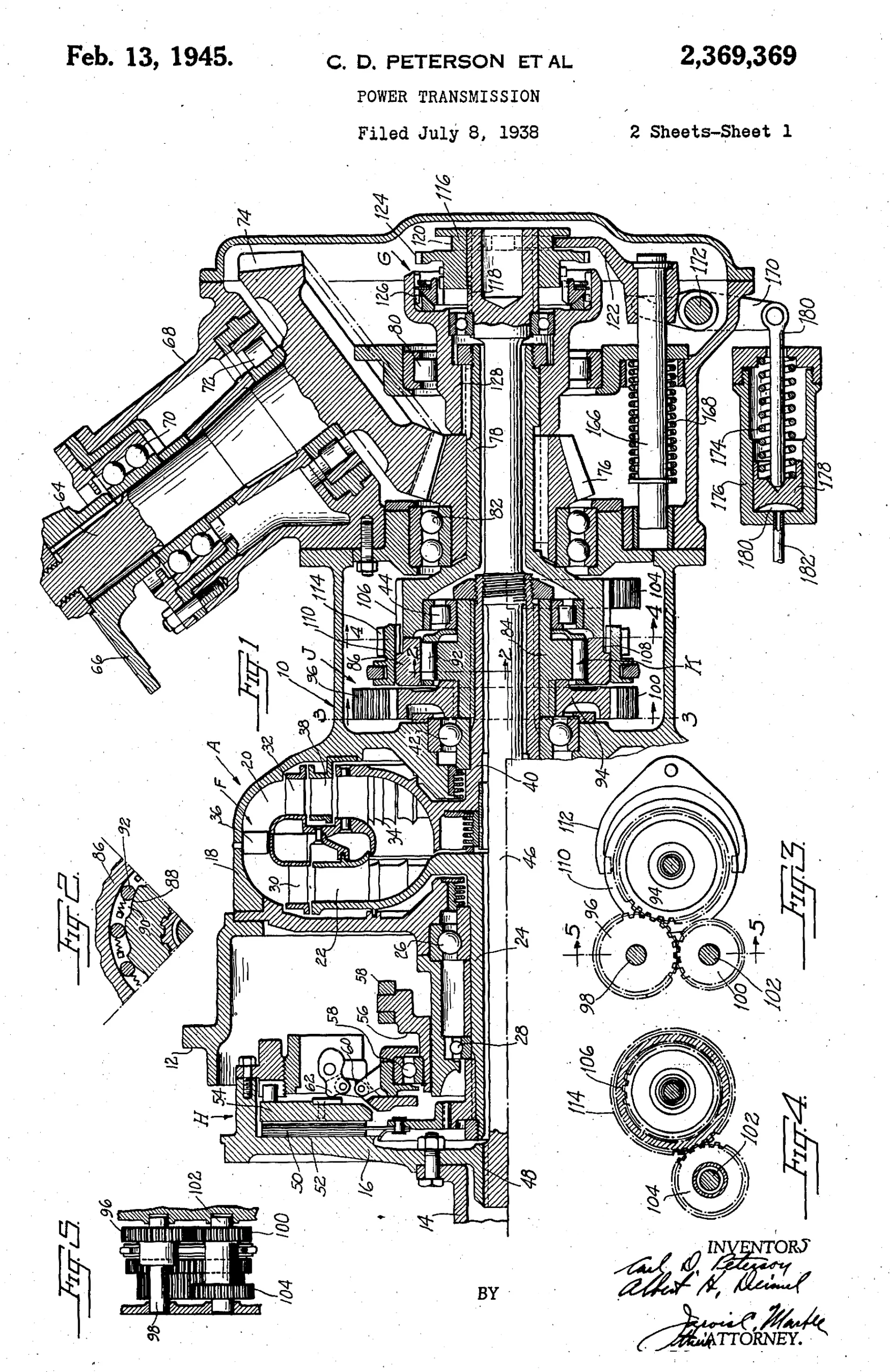
Spicer licensed the Lysholm patents and began work on an American version of the hydraulic transmission around 1934. Although the underlying design was still Lysholm’s, both Spicer and Yellow Coach were able to obtain various patents on their version and its controls. The Spicer patents were filed by Carl D. Peterson and Albert H. Deimel, while the Yellow Coach patents were by Hans O. Schjolin. Two buses equipped with prototype transmissions were put into actual service in New York and Chicago for testing under real-world conditions, leading to some further design changes before production.
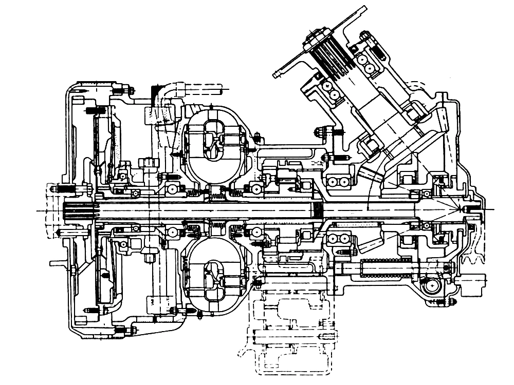
The first production version of the Spicer hydraulic transmission, the Model 90, became available in December 1938 for Yellow Coach Model 732 and Model 740 buses.
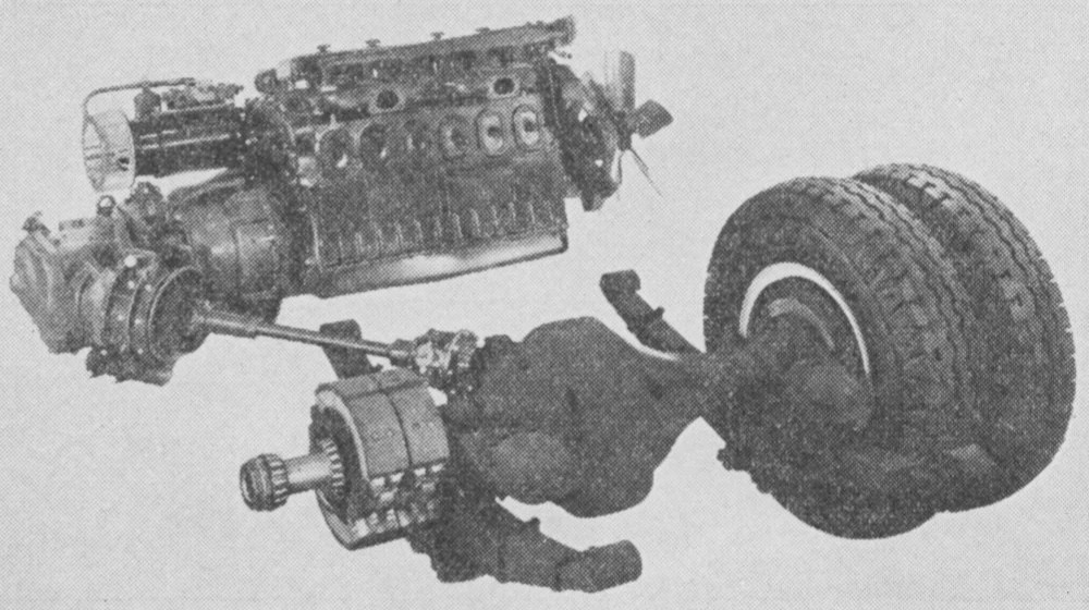
At first, the hydraulic drive was usually paired with Yellow’s 707 cid six-cylinder gas engine, but in 1939, Yellow Coach and Spicer also modified the transmission so it could be used with the new 426 cid Detroit Diesel 6-71 two-stroke diesel engine.
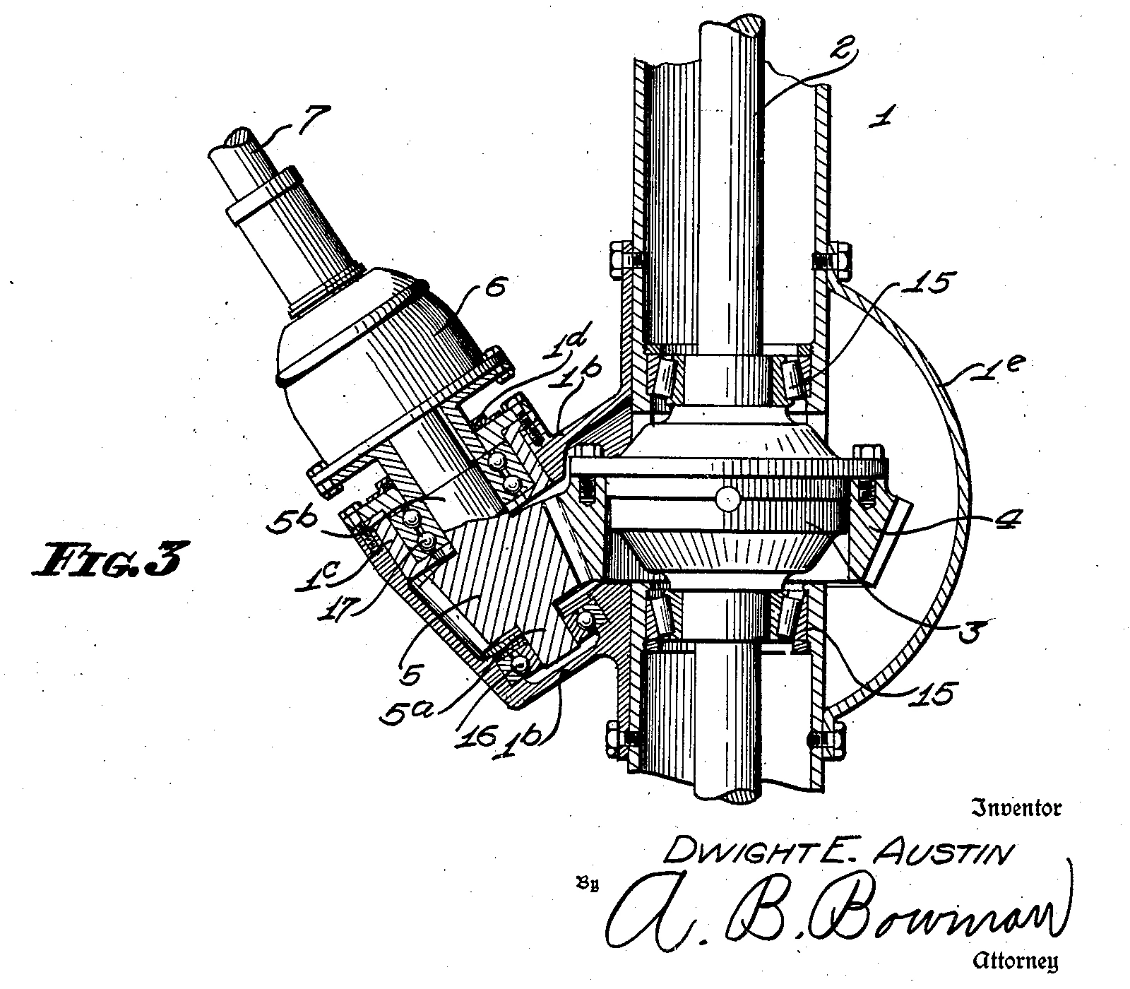
These buses were rear-engine, with GM’s patented “angle drive,” developed for Yellow Coach in the early 1930s by Dwight E. Austin (and patented as US1993912). The engines were transversely mounted at the very rear of the coach, with the transmission shafts in the same plane as the engine crankshaft, outputting through bevel gears to a propeller shaft set at an angle of either 52 or 90 degrees.
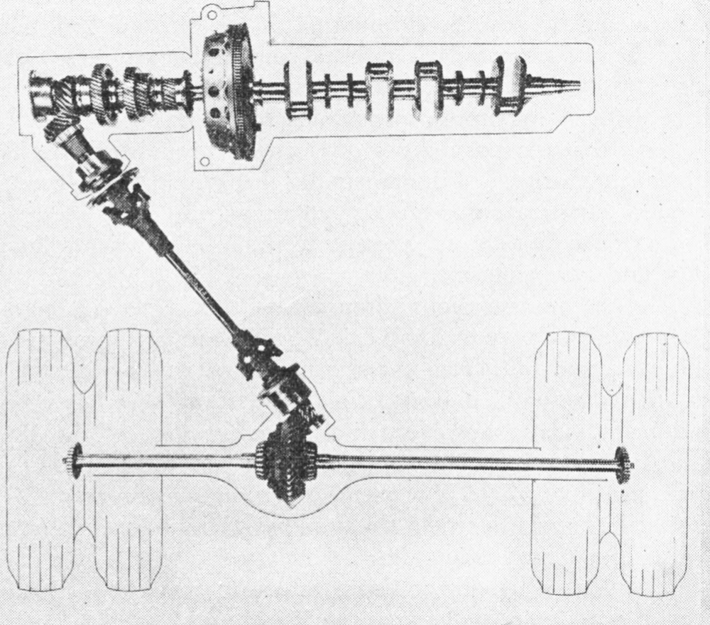
With 3- or 4-speed synchromesh transmissions, complex remote linkages were required to allow the driver, seated in front, to control the rear-mounted gearshift and clutch. Achieving smooth shifts and clutch engagements with mechanical bus transmissions took real skill, and the constant shifts required to keep up with city traffic was hard on the machinery. “Operators often resort to clash shifting on grades in order to shift into the next higher gear before vehicle has lost momentum and corresponding engine speed is too low to deliver power required,” noted Spicer engineer Robert R. Burkhalter in a 1944 presentation.
It was for that reason that Yellow Coach insisted on fully automatic clutch controls for its hydraulic drive, rather than the manually operated direct drive system of the Leyland transmission. According to Green, Yellow had concluded that “the ideal form of transmission for city service vehicles should be fully automatic, quiet, light in weight, one which does not need any particular skill to insure satisfactory operation.”
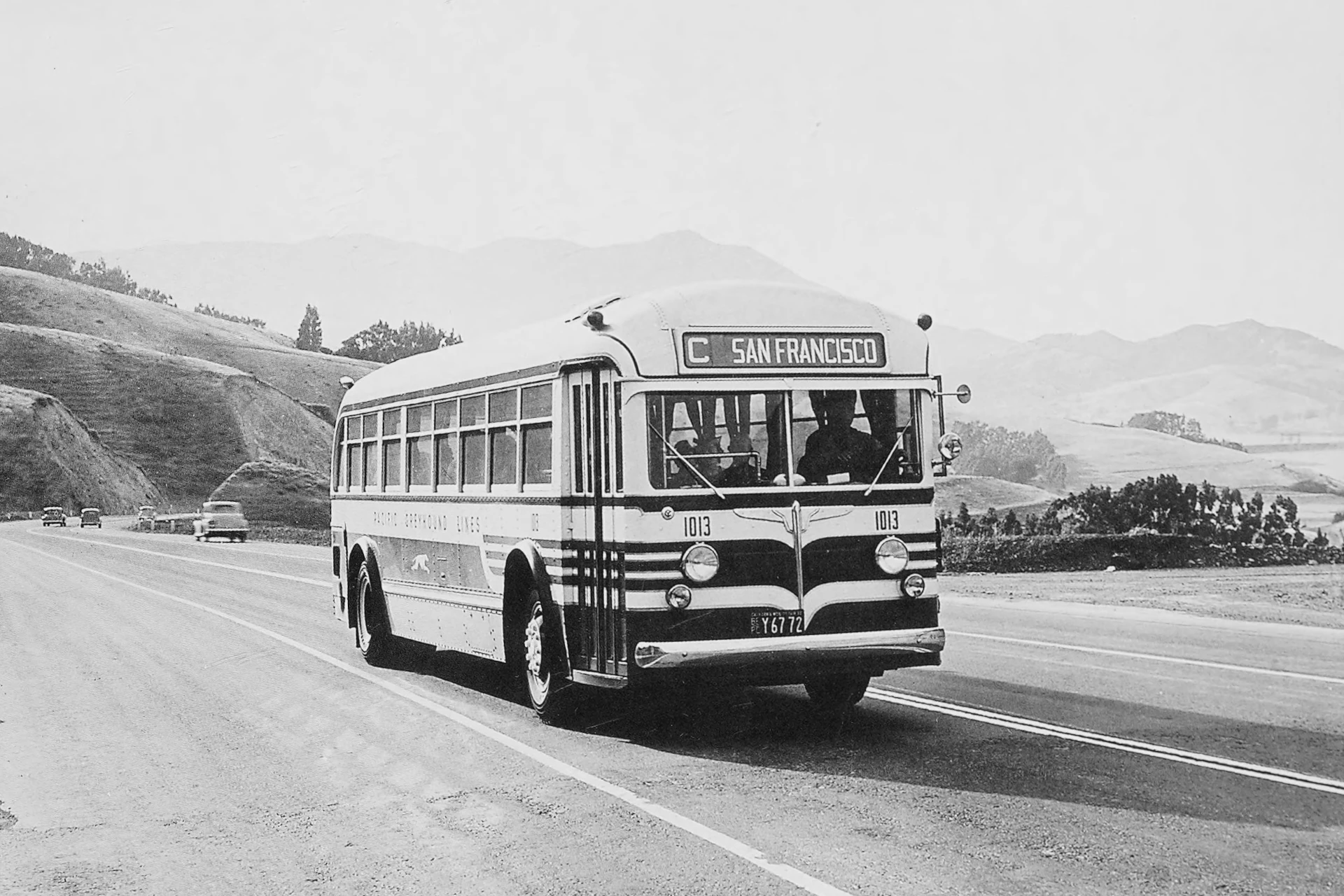
Although some operators used it in suburban service, Yellow Coach developed the hydraulic transmission specifically for transit buses, and its maximum governed speeds (officially 47 mph with gas engines, 53 mph with diesels) were really too low for intercity use. Green explained:
Our development of the hydraulic transmission was based on its use for congested city-service operation where there are vast numbers of starts and stops. In this class of service any form of transmission is really a device to facilitate the rapid and smooth acceleration of the vehicle and, in this respect, the results attained with the hydraulic transmission are superior to any form of gear transmission with which we are familiar. It is possible that the hydraulic transmission might be entirely satisfactory for interurban use where there are heavy grades but, since up to the present we have not contemplated the use of the hydraulic system in this class of service, we cannot state with authority if it would or would not be satisfactory.
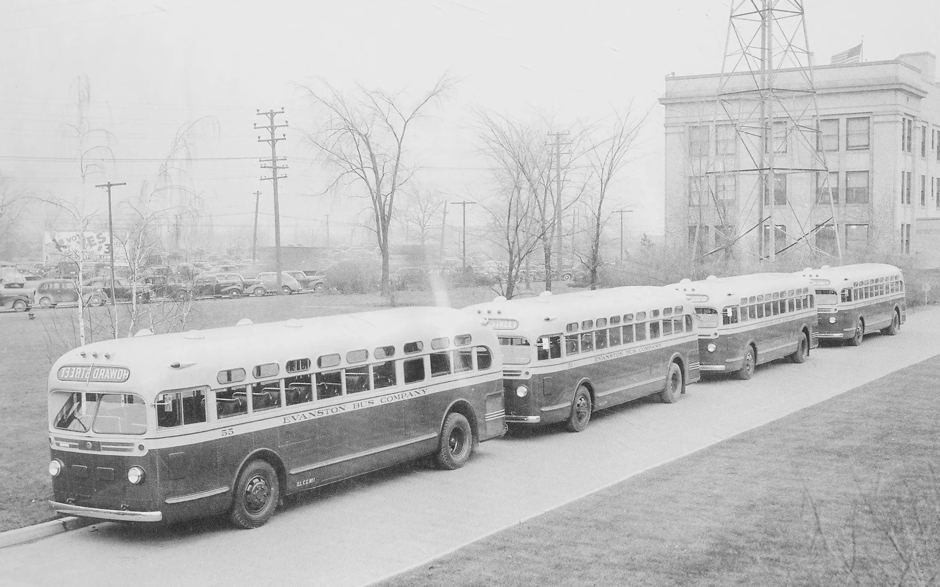
In 1940, Spicer and Yellow Coach introduced a second version of the hydraulic transmission, the Model 91, for smaller transit coaches powered by the 284 cid four-cylinder 4-71 diesel or 451 cid gas engines. The Model 91 transmission worked the same as the Model 90, except in minor details, but it had a longer case with some rearranged components so that the angle drive gears could be mounted at the same angle as six-cylinder coaches even with the shorter four-cylinder engine.
Hydraulic Transmission in Operation
The Spicer hydraulic bus transmissions were designed to occupy about the same space as a conventional clutch and gearbox, and the Model 90 was only about a pound and a half heavier. The biggest tip-offs that a coach had hydraulic drive were that there was no clutch pedal, and the shift lever had only three positions: Forward, Neutral, and Reverse.
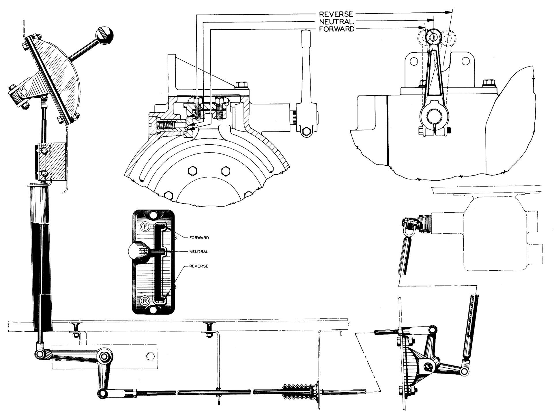
Operating the hydraulic transmission was simple: The driver moved the shift lever slowly into Forward and pressed the accelerator. The bus then took off with smooth flow of power from the torque converter. At a predetermined road speed, usually 21 mph, drive to the torque converter would automatically cut out and the direct drive clutch would engage, letting the converter slow to a halt while the engine drove the output shaft directly. If road speed dropped below a certain speed — initially 17 mph, reduced to about 14 mph on later transmissions — the direct drive clutch would automatically release, bringing the torque converter back into operation.
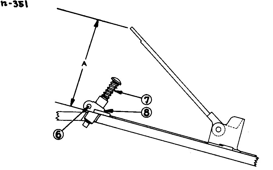
There was also an “overrule switch” under the accelerator pedal, activated by pushing the pedal all the way to the floor. Engaging the overrule switch forced the transmission to drive through the torque converter — if the transmission was in direct drive, the overrule switch would cause it to return to hydraulic drive, and if it was already in hydraulic drive, it would stay there. This ensured that the torque converter would be available in situations like climbing a hill at 20 to 25 mph speeds, where the transmission might otherwise go into direct drive prematurely.
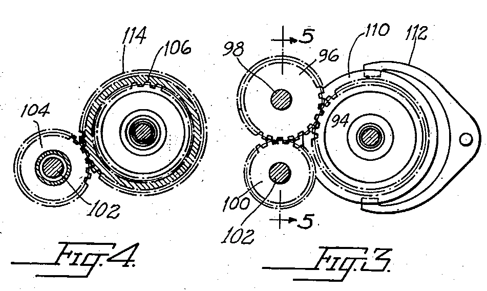
The trickiest aspect of driving this transmission was engaging Reverse. The spur gears for reverse were mounted between the torque converter and the angle drive. Unlike the Leyland transmission, the reverse gears in the Spicer units were not synchronized, so the manual recommended moving the shift lever to Forward and then rapidly shifting to Reverse to get the reverse gears to engage without clashing. However, usual transit bus routes didn’t use Reverse very often. Neutral was normally only needed if the driver needed to leave their seat with the engine running, to keep the coach from creeping at idle.
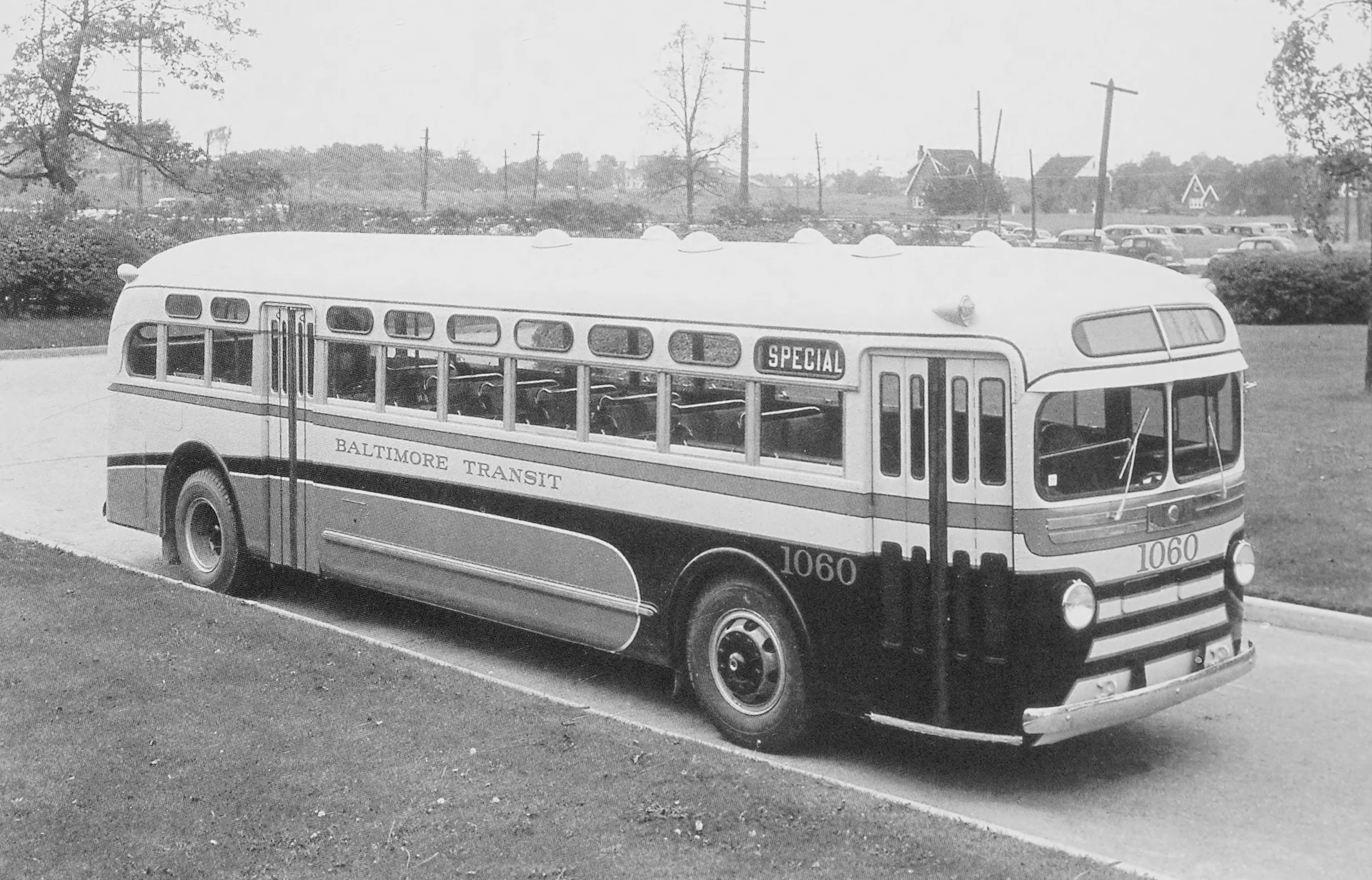
Hydraulic transmission made Yellow Coach transit buses more pleasant to ride in and much easier to drive. One of the initial selling points for transit operators was that the hydraulic transmission freed bus drivers to make change for passengers. Transport workers unions had been pushing for city bus companies to add conductors to handle fares and change, arguing that it was very difficult for drivers to do that and still manage constant gear-shifting in city traffic. While the hydraulic transmission cost more than a mechanical transmission upfront, it was cheaper than a conductor’s salary.
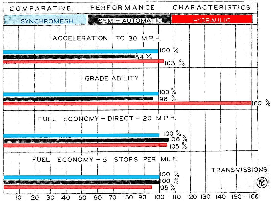
At a rate of five stops per mile, the torque converter transmission used slightly more fuel than a mechanical transmission, but overall fuel consumption was about the same. Over time, the cushioning effect of the converter also paid off in reduced wear and tear. “The elimination of shock loading has shown a definite increase in life of engine, clutches, gear boxes, propeller shafts, axles and tires,” Burkhalter reported in 1944. “Bus operators report an interesting sidelight on the safety feature of smooth starting, in the reduction of claims for passenger injuries, which is worthy of consideration.”
Inner Workings of the Spicer Hydraulic Transmission
In the Spicer hydraulic transmissions, torque multiplication was provided by the torque converter and the angle drive gears, so the only actual gear-shifting involved was for reverse.
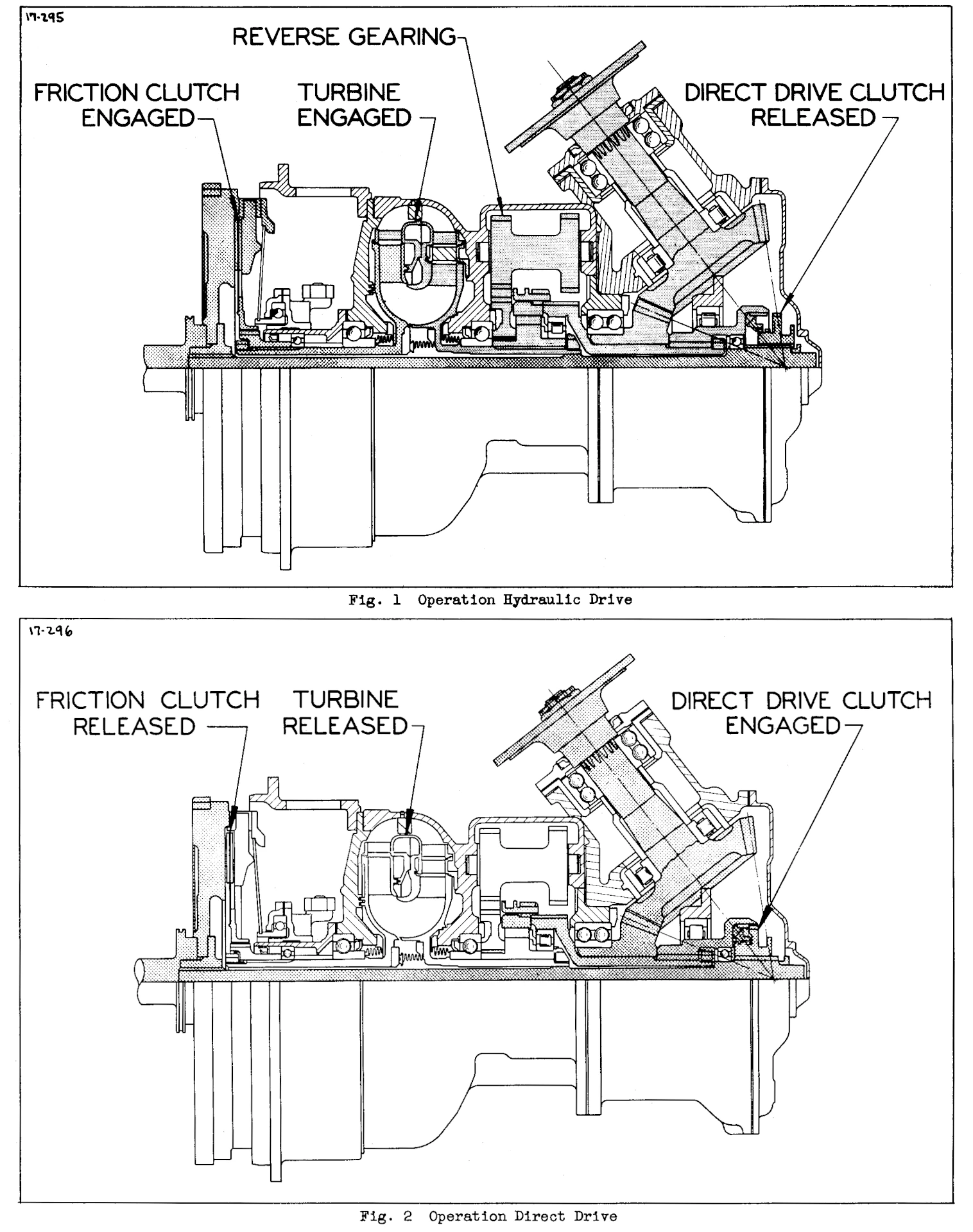
The transmission was controlled with three clutches: the hydraulic drive clutch (called the friction clutch in early transmissions), the direct drive clutch, and an overrunning clutch that connected the converter turbine to the output shaft.
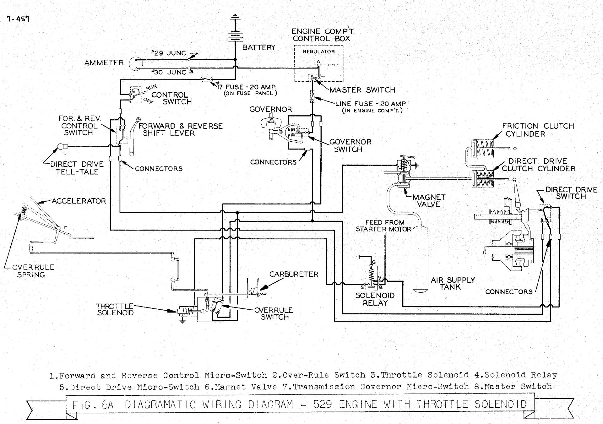
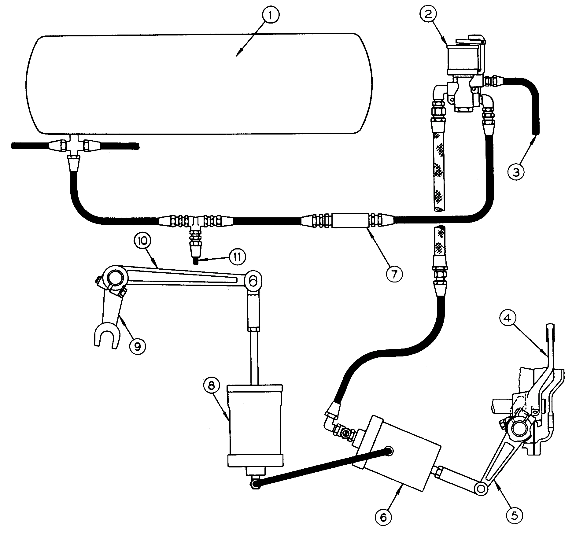
The control system was electro-pneumatic, using an electrically triggered magnet valve to admit or exhaust compressed air for the clutch control cylinders that operated the hydraulic drive and direct drive clutches. A micro-switch in the shift tower controlled the flow of current to the magnet valve, keeping both clutches in their released position when the engine was running and the shift lever was in Neutral.
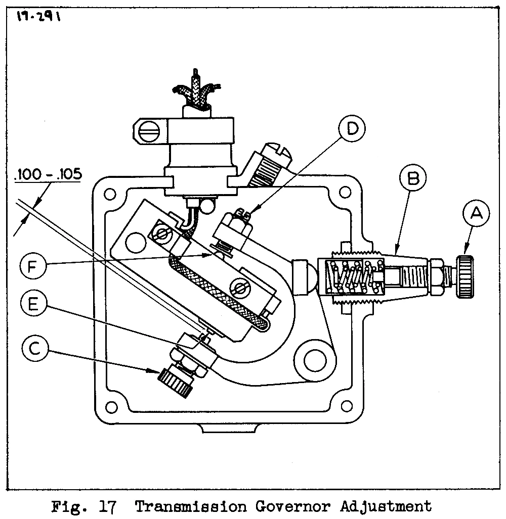
A governor driven by the angle drive gears engaged an electrical switch when the coach reached a specific road speed, triggering the engagement of the direct drive clutch. This switch would open again if the coach slowed enough. (The disengagement speed was set lower than the engagement speed to avoid “hunting.”) There were adjustment screws to allow the engagement speed of the governor to be raised or lowered.
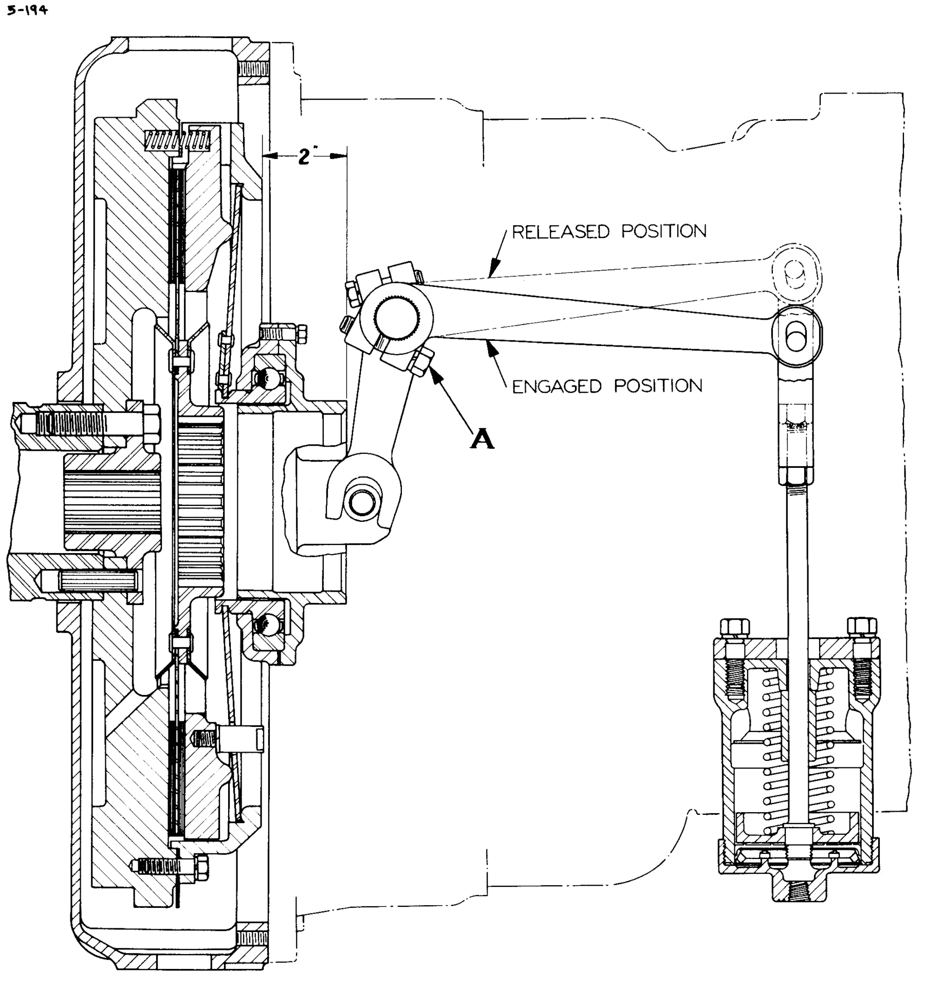
This service manual illustration shows how the hydraulic drive clutch was engaged or disengaged by the pneumatic control cylinder (at the lower right).
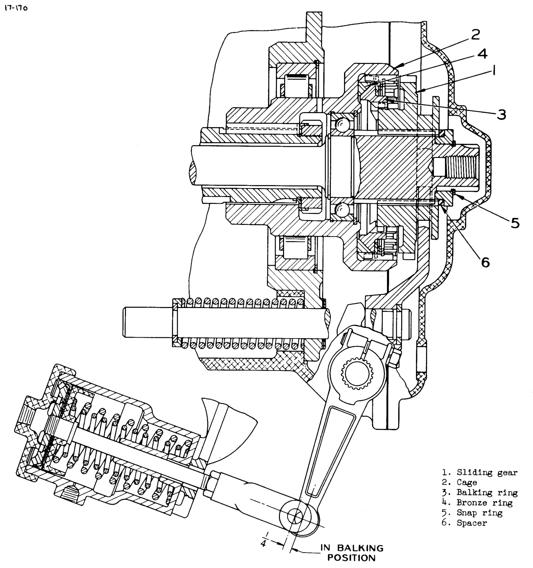
Early Spicer hydraulic transmissions had a positive-acting jaw-type direct clutch, with a sliding gear engaging with an internally toothed cage.
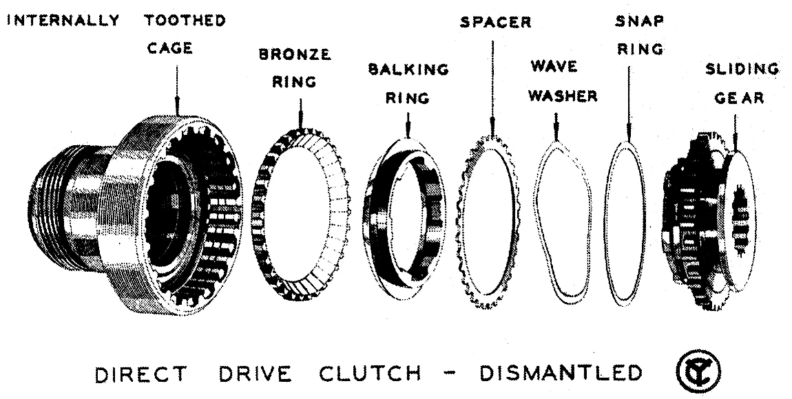
This clutch really worked more like high gear in a synchromesh manual transmission. A balking ring prevented the sliding gears from meshing until their speeds matched. This was supposed to keep clutch wear to a minimum.
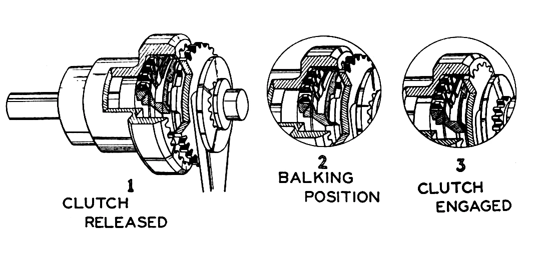
For the synchronized direct clutch to engage, engine power had to be interrupted briefly with the clutch in the balking position so that the speeds of the gears could equalize.
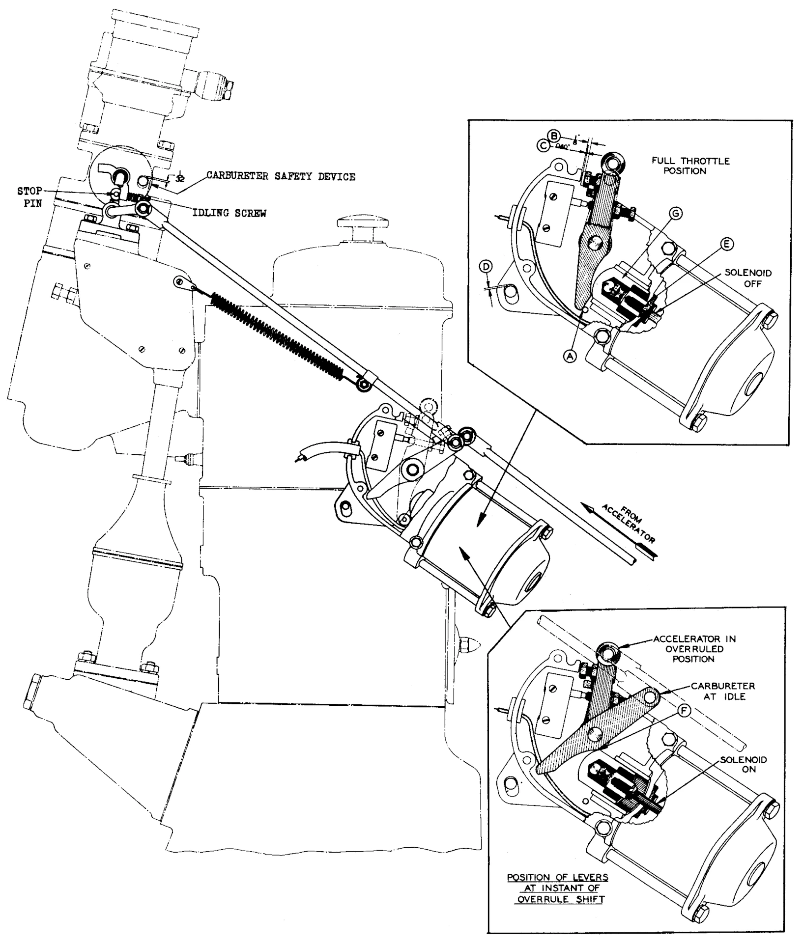
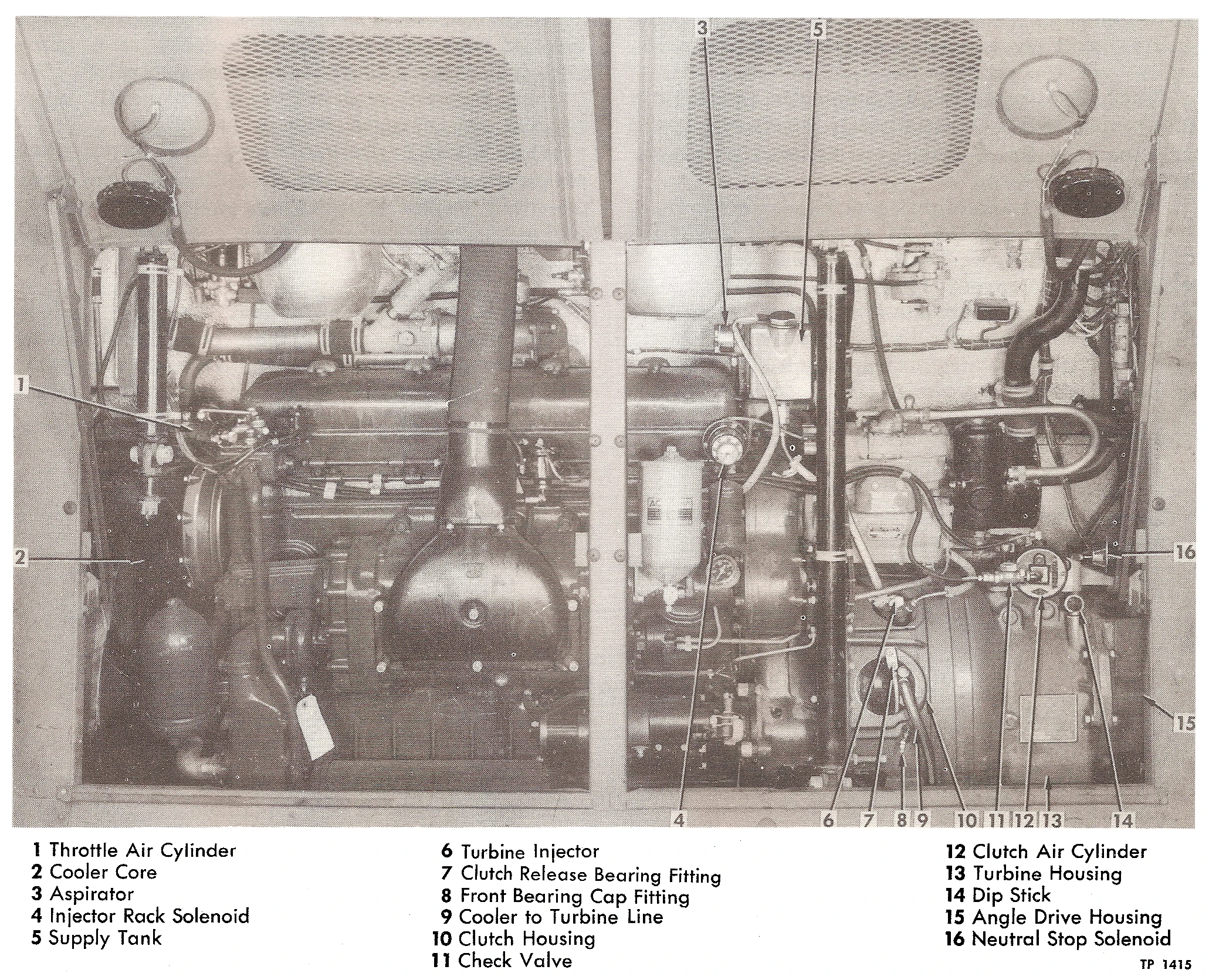
Cutting engine power during shifts into or out of direct drive was originally accomplished using a solenoid on the carburetor throttle linkage (on gas coaches) or the injector rack (on diesel coaches), which closed the throttle or moved the injector controls to its no-fuel position. Later Model 90 and Model 91 transmissions instead used an additional air cylinder and magnet valve to do the same thing. Either way, the interruption of power happened automatically; the driver didn’t have to lift off the accelerator pedal.
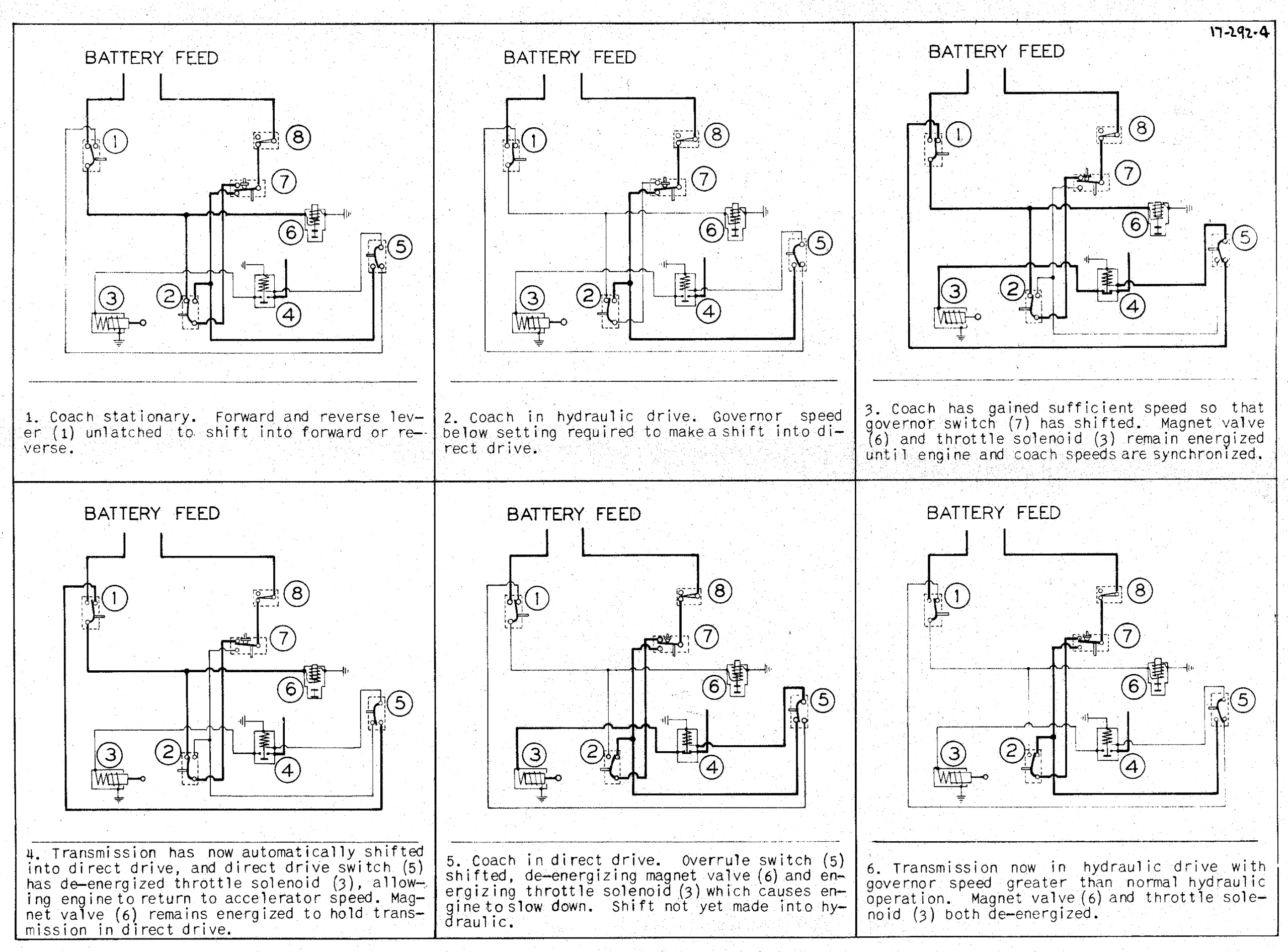
A shift to direct drive worked like this:
- At a predetermined speed, the governor switch closed, energizing the throttle control solenoid (or second magnet valve).
- The throttle closed or the injector rack moved to no-fuel, cutting off engine power.
- Current flowed to the magnet valve to admit air to the clutch control cylinders.
- The hydraulic drive clutch released, disconnecting the torque converter pump from the engine.
- The direct drive clutch moved to its balking position.
- Once the speeds matched, the balk ring allowed the sliding gear to mesh with the clutch cage, connecting the engine to directly to the output shaft via the overrunning clutch.
- A switch on the direct drive clutch shaft de-energized the solenoid and magnet valve(s), causing the throttle or injector rack to return to its previous setting.
- With no drive to the pump and the turbine shaft freewheeling relative to the output shaft, fluid drag caused the converter to slow to a halt.
Shifting from direct drive back to the torque converter involved the same steps, but in reverse order.
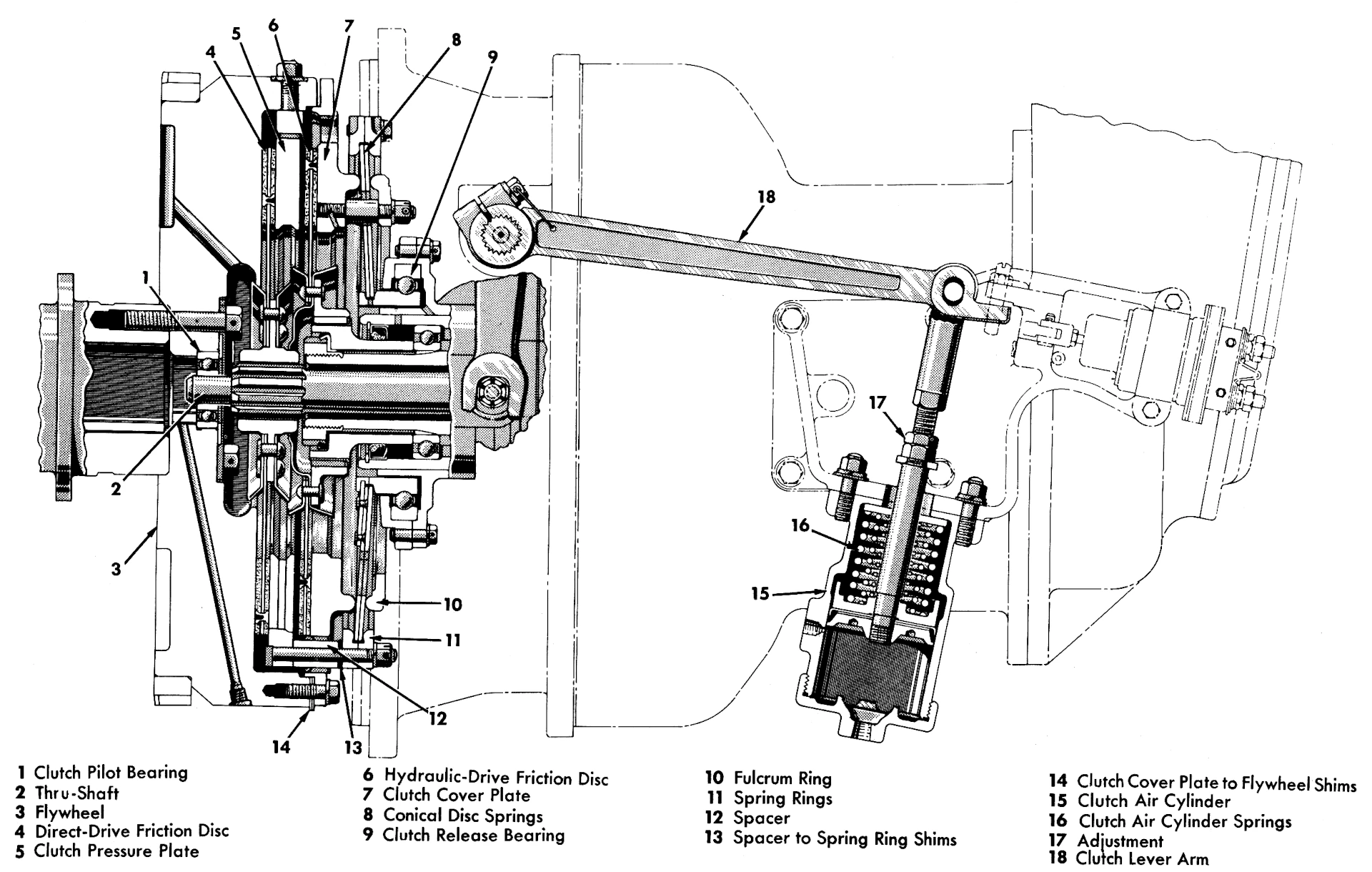
Around 1942, Spicer introduced a new dual-clutch arrangement for the hydraulic transmissions, more like the Leyland transmission and Lysholm’s original design. This eliminated the previous jaw-type direct drive gears in favor of a second plate clutch. It was mounted next to the hydraulic drive clutch, using the same pressure plate, which was engaged with dual conical springs. Moving the lever all the way to one end of its travel engaged one clutch and released the other. This arrangement allowed both clutches to share the same lever arm and control cylinder.
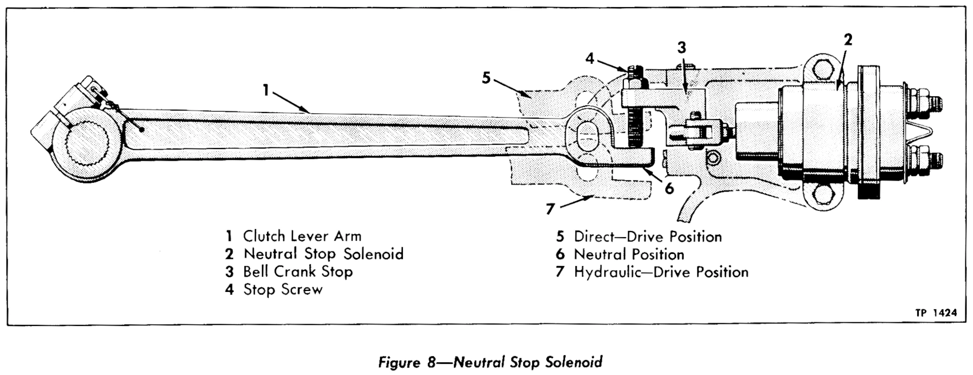
With the dual clutches, there was an additional neutral stop solenoid that energized in Neutral, moving a bell crank that would trap the clutch lever in the middle position, preventing it from engaging either clutch. Transmissions with dual clutches also had a pressure switch in the turbine cooler line that prevented direct drive clutch engagement unless there was at least 28 psi pressure in the torque converter. (I think this was an additional safeguard to keep the direct clutch from engaging in situations where it might stall the engine.)
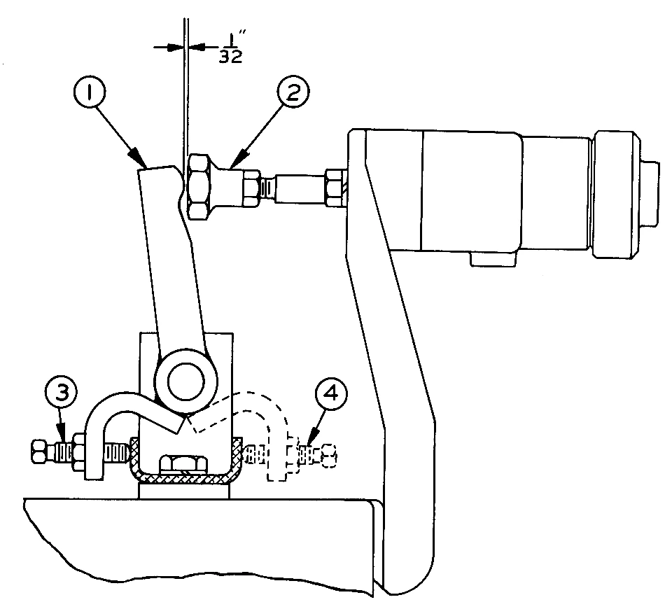
Dual-clutch transmissions still interrupted engine power temporarily when engaging or disengaging the direct clutch. The dual plate clutches didn’t need to synchronize speeds the way the balk-ring direct drive gear did, but interrupting power during clutch engagement or disengagement reduced clutch wear.
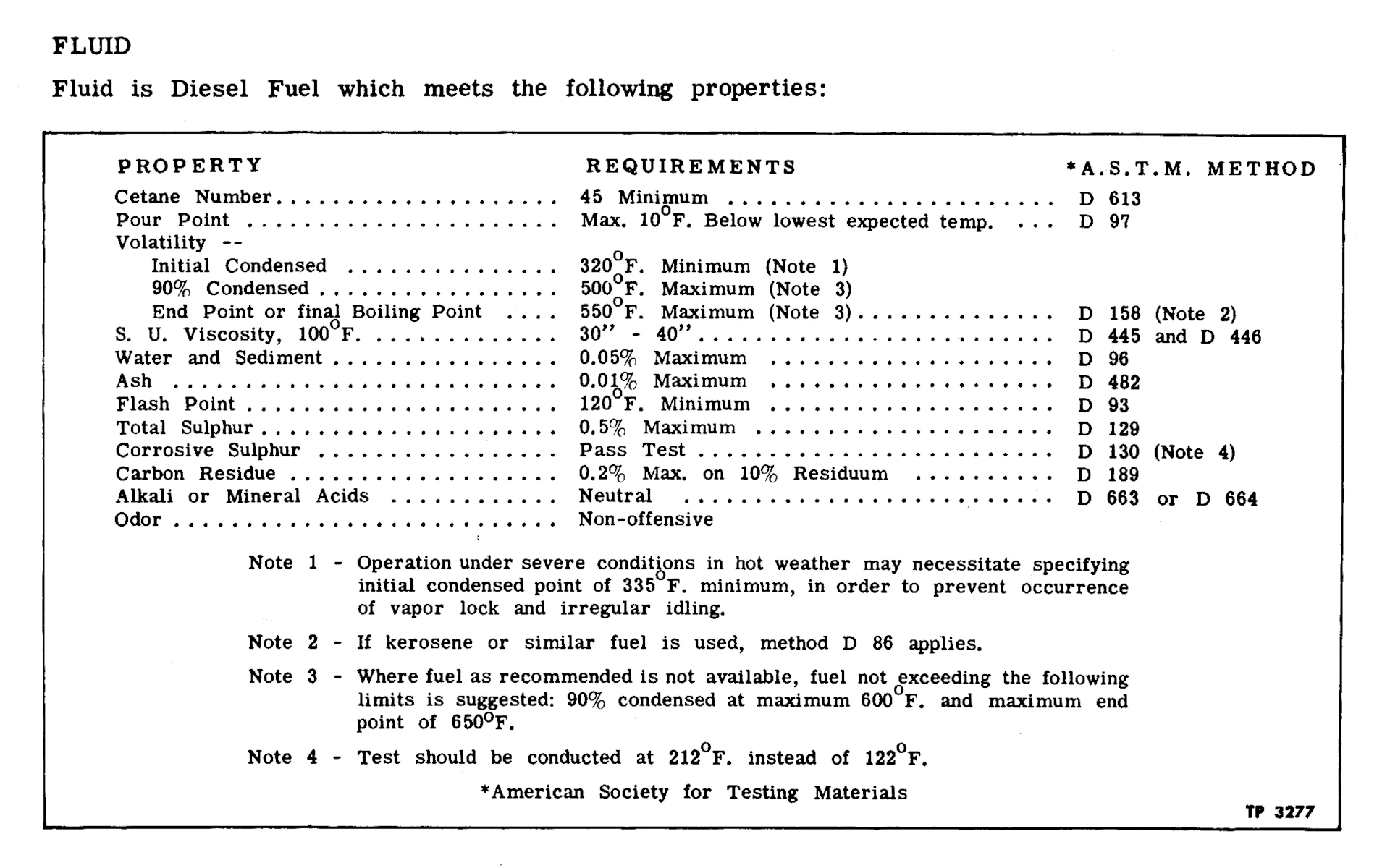
The torque converter fluid in these early hydraulic transmissions was typically diesel fuel. By the 1950s, there would be automatic transmission fluids specifically designed for truck and bus transmissions, but, as Spicer engineers Edward W. Zingsheim and Myron M. Schall explained in a 1954 presentation, “The oil companies were not interested in developing a special fluid for this operation until a relatively large number of units were in service and production of torque converters for buses had increased.”
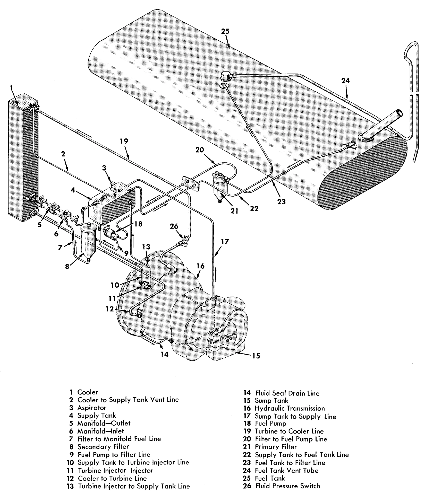
Gas coaches had a separate fluid supply tank for the converter, but on diesel coaches with hydraulic transmission, the fluid system for the torque converter was actually integrated with the engine fuel supply! For diesel-powered buses, this was convenient, since there was no need to change or replenish a separate oil supply for the transmission, but it caused a lot of problems. Although the torque converter passed its fluid through an oil cooler before returning it to the tank, excess heat tended to oxidize the fuel, and the “considerable variation” in the quality of contemporary diesel could lead to sludge, varnish, and blockages. Also, with the diesel fuel, care had to be taken that converter fluid didn’t mix with the lubricating oil of the mechanical gears. (Later GM hydraulic transmissions used the same oil for the gears as for the torque converter, and no longer used diesel fuel.)
Replacement by V Drive
Between 1938 and 1948, the Spicer Model 90 and Model 91 hydraulic transmissions were installed in about 14,000 transit buses, including many of the GM “Old Look” T series. (After WW2, GMC began applying an “H” to the model designation of coaches with the hydraulic transmission, although it doesn’t appear they did that initially.)
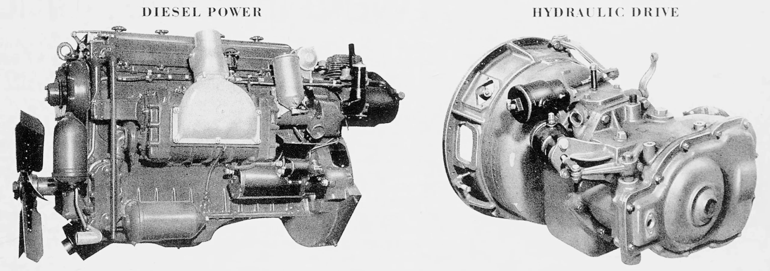
The hydraulic transmission became increasingly popular with transit companies, especially in combination with the Series 71 diesel engines. Operators found that the later transmissions were good for about 80,000 miles between overhauls, and their cushioning effect reduced wear in other areas.
Yellow Coach/GMC had started thinking about a more extensively revised hydraulic transmission around 1942, but the war and corporate politics intervened. After the war ended in 1945, GMC had asked the corporation for space and funding to build a new hydraulic bus transmission, possibly accompanied by a new intercity bus transmission intended for Greyhound. However, Allison Division was lobbying to become GM’s heavy-duty transmission division, so in June 1946, Allison took over the bus transmission project. The Greyhound proposal was dropped.
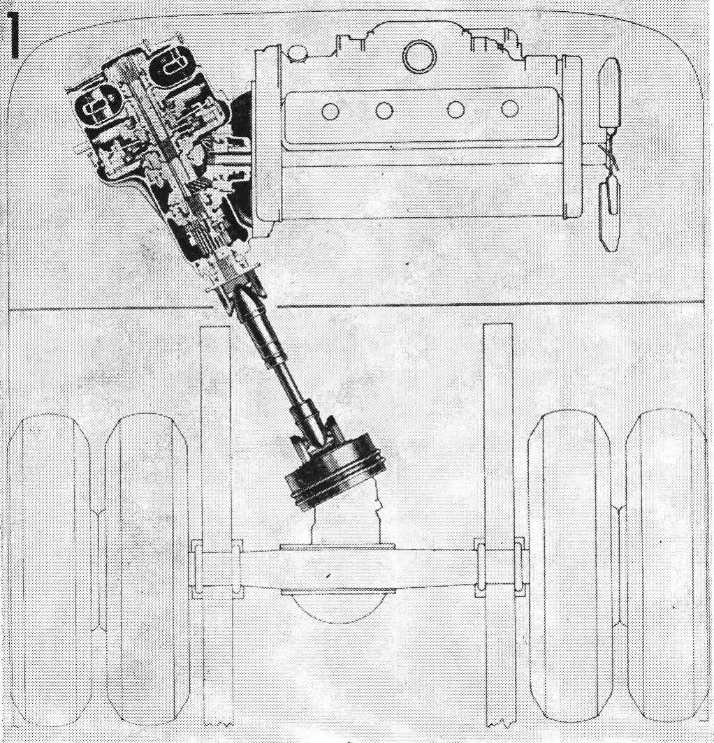
In late 1947, Allison built the first production examples of the new “V-drive” hydraulic transmission. Designed primarily by Hans Schjolin of GMC Truck and Coach, who had also done much of the design work on the Model 90 and Model 91, the early V-drive transmission was similar to the dual-clutch Spicer hydraulic drive in basic principles and operation, but the components were laid out differently. Now, the entire transmission was mounted at an angle, connected to the engine through bevel gears. The new transmission was in full production by late 1948, replacing the Spicer units. GM produced the Allison V-drive, in several distinct versions, into the mid-1970s.
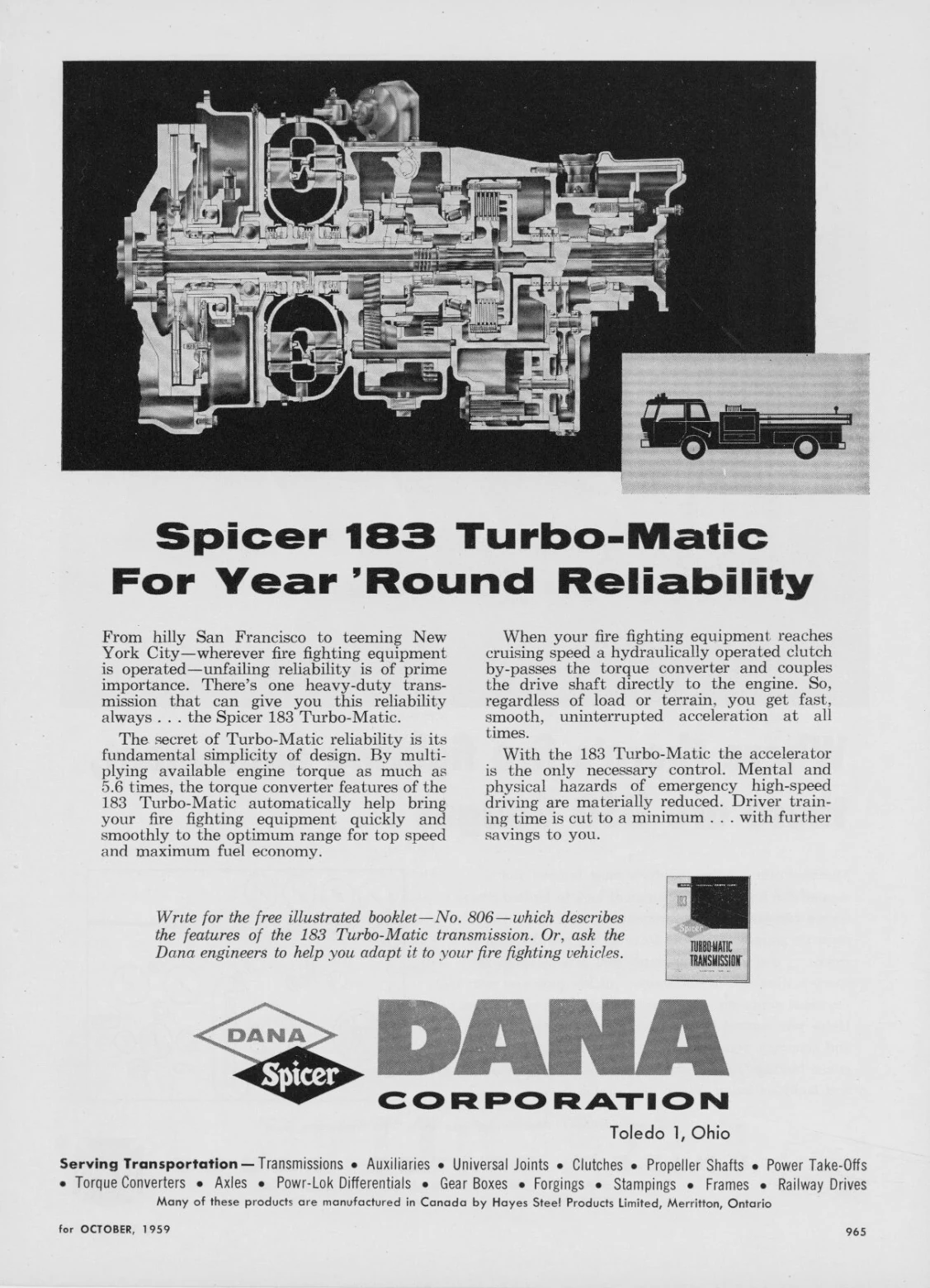
Spicer, which became a division of Dana Corporation in 1946, continued building torque converters and torque converter transmissions for other manufacturers and other applications, like mining trucks and fire trucks.
The Model 90 hydraulic transmission wasn’t the first torque converter bus transmission, nor was it even the first Yellow Coach automatic transmission (a few hundred mid-1930s coaches had used Oscar Banker’s Mono-Drive semiautomatic transmission). However, it was an important step in city bus development, and the diesel/hydraulic drive combination was one of the reasons GM so dominated the field for many years. While torque converter transmissions proved to be a mixed blessing for passenger cars, for coach use, the advantages outweighed the drawbacks.
Related Reading
GMC TDH-5105 Old Look Transit Bus: GM’s Greatest Hit #9 — Despite Being the Agent of a GM Deadly Sin (by Paul N)
GM Yellow Coach Hydraulic Transmission Model 90 Maintenance Manual ( X 4112, 1941) (at the Internet Archive)
GM Coach Hydraulic Transmission Models 90 And 91 Maintenance Manual ( X 4512 A B C, 1945) (at the Internet Archive)











Are we really supposed to be able to read this highly informative technological tutorial with the incessant annoyance of pop up ads here for stuff?