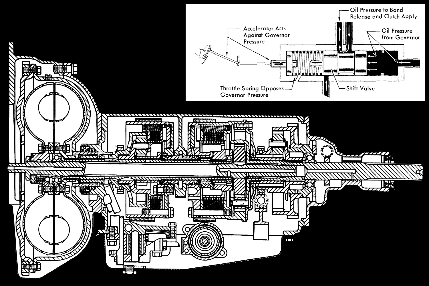
A lot of car buffs understand engines pretty well, but seem to blank out when it comes to automatic transmissions and how they change gears. Today, we can cheat a bit and say, “Well, the computer does it,” but what about the 40 or 50 years of automatic-transmission cars built before electronic controls became universal? Here’s how most automatic transmissions since the original 1940 Hydra-Matic have “decided” when to shift — which even in those pre-electronic days was more computerized than you might think.
Early Automatic Transmission Attempts
Almost from the earliest days of the automobile, there were efforts to create transmissions that could shift for themselves. Well before the introduction of GM’s Hydra-Matic transmission for the 1940 model year, there were dozens of different automatic transmission designs, using a dizzying array of different strategies, layouts, and control mechanisms. None really caught on, and most were complete failures — some due to excessive cost or weight, some due to unacceptable fragility, and some because they simply didn’t work very well when put to the test.
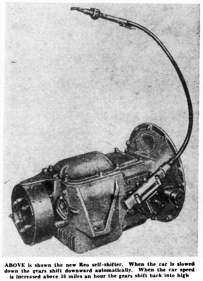
For change-speed transmissions (that is, transmissions with a discrete number of forward gears, as opposed to continuously variable transmissions), the biggest fundamental problem was finding an effective, reliable way to get the transmission to automatically shift up or shift down at appropriate times.
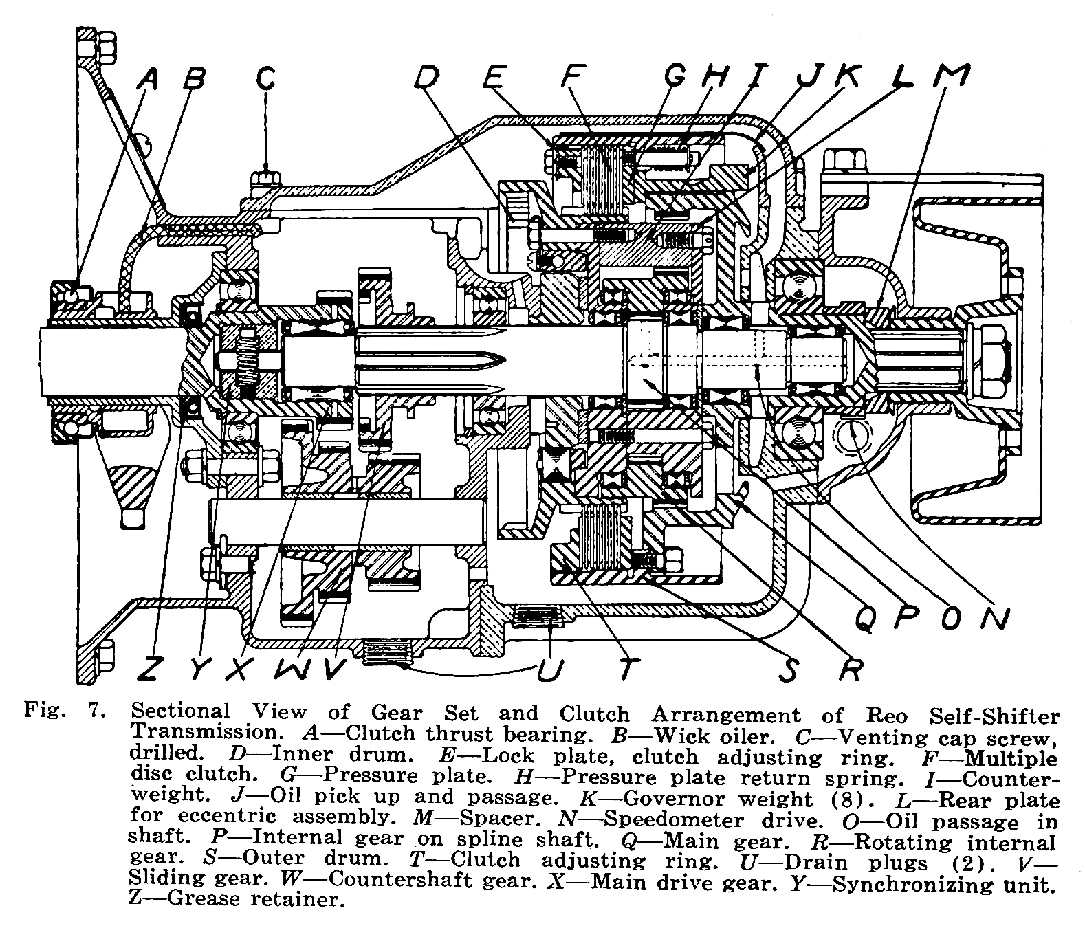
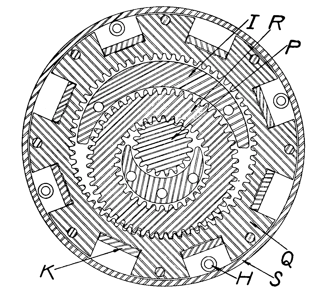
Many early change-speed automatic transmissions, like the Sturtevant automatic or the Self-Shifter that Reo introduced in May 1933 (pictured above), were centrifugally controlled: They had governors driven either by the engine or off the output shaft, using weights that moved outward with increasing speed to engage clutches or brakes. This worked to a point, but with purely centrifugal controls, shift points are largely fixed — that is, the transmission will always upshift or downshift at certain engine speeds or road speeds. Fixed shift points are always a compromise, and sometimes a very poor one.
In a car or truck with an engine and a change-speed transmission, the best gear to be in for any given situation often depends on load, or what engineers sometimes call “torque demand.” When you’re driving gently along a level road at a constant speed, you really only need enough power to overcome friction and aerodynamic drag at your current speed (which engineers call “road load”), and it’s usually better to be in a higher gear in order to keep engine speed low and reduce fuel consumption and noise. If you suddenly need to accelerate or climb a steep grade, torque demand increases, making it desirable to be in a lower gear that provides more torque multiplication and a higher engine speed for a given road speed.
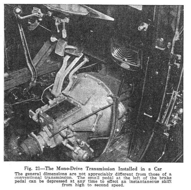
For almost anyone who knows how to drive, all of that is pretty self-explanatory even if you’ve never heard the phrase “torque demand.” The bigger problem was how to design an automatic mechanism that could reliably select different gears based on both speed AND load — what engineers sometimes call “divergent modulation.” Mechanical controls based on centrifugal force couldn’t really do that very well. Generally, those transmissions would only downshift under load if current torque demand was great enough that the vehicle started to slow down, and they often required some positive action from the driver to execute gear changes, making them semiautomatic rather than truly automatic. The Banker Mono-Drive transmission, for example, needed a separate foot pedal to downshift for passing.
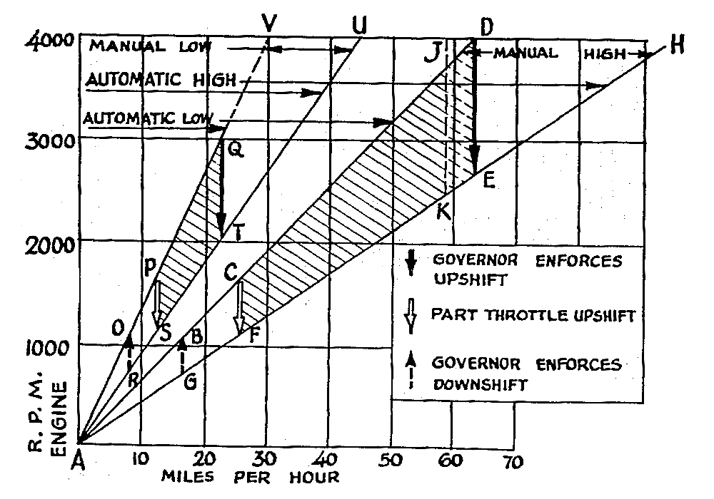
The divergent modulation shift strategy adopted for most fully automatic change-speed transmissions between 1940 and the 1980s was first devised in the late 1930s by a GM Engineering Staff product study group led by Earl A. Thompson, inventor of Synchro-Mesh. This group developed the 1937–1939 semiautomatic transmission (called the Automatic Safety Transmission by Oldsmobile, the Self-Shifting Transmission by Buick) and then the first 1940 Hydra-Matic.
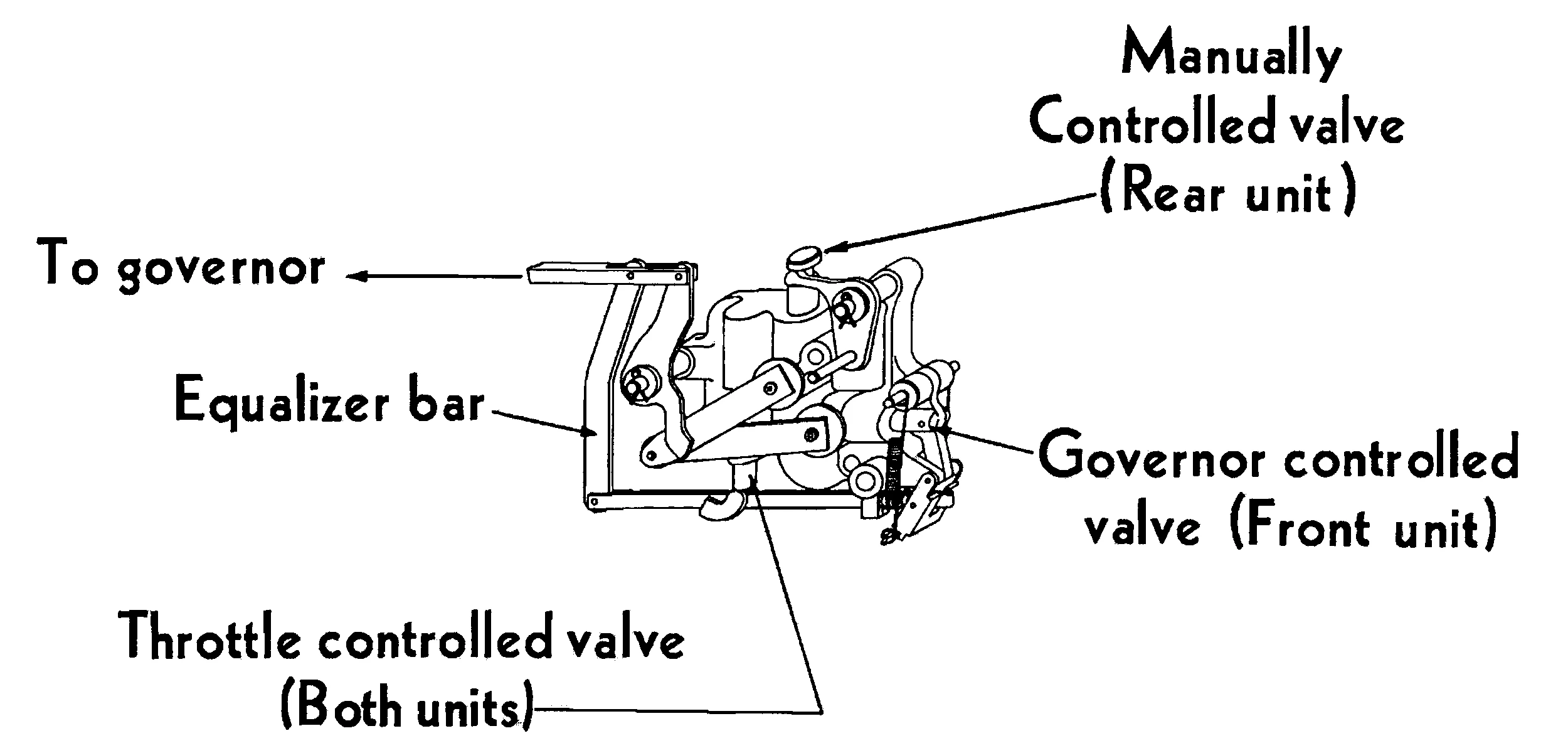
Although the GM semiautomatic transmission controls involved some basic concepts that were broadly similar to the later Hydra-Matic, the semiautomatic relied on mechanical linkages, which could really only work for two speeds. (The GM semiautomatic transmission had four speeds, but the transmission could only shift automatically between two of them; the driver had to manually shift between Lo and High ranges, with automatic shifts in each range.) The 1940 Hydra-Matic introduced an almost completely new hydraulic control system based on a concept of opposing forces. This became one of the most important and influential developments in automotive transmission design in the 20th century.
Opposing-Forces Shifting Explained

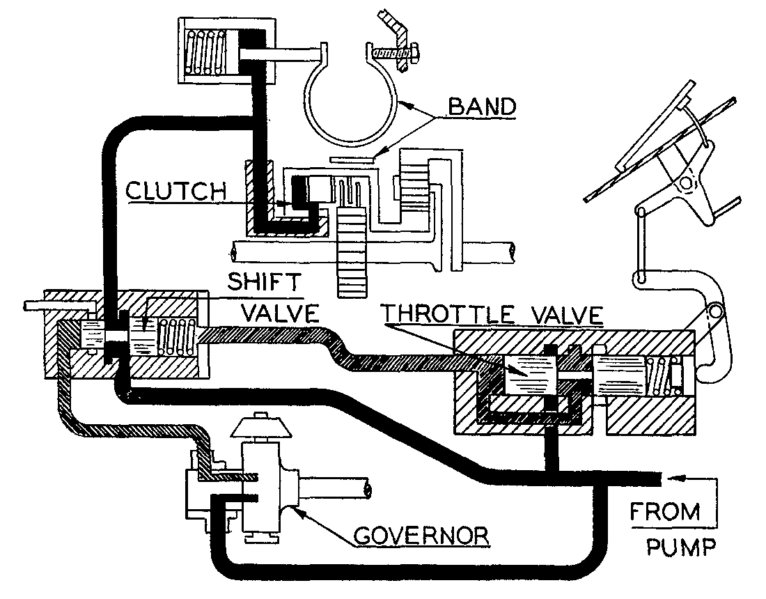
Even early fully automatic transmissions are extremely complicated, and it’s easy to get lost in the details. To understand the control logic I’m about to explain, all you really need to know is that in these transmissions, each gear ratio is created by using hydraulic pressure to engage or release certain brakes and clutches. Thus, changes between gears are accomplished by using shift valves to apply or cut off oil pressure to those elements in different combinations.
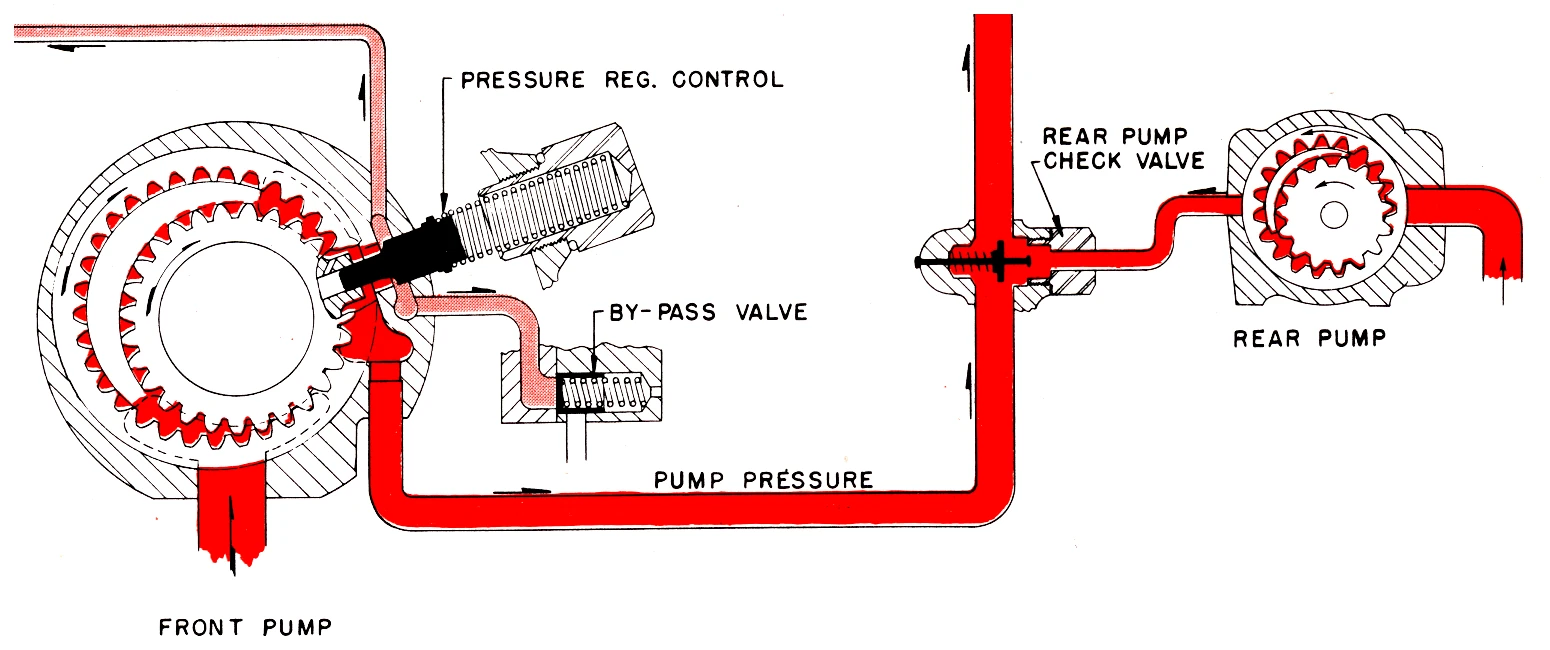
The first thing ones of these transmissions needs to be able to shift for itself is at least one oil pump that can generate the necessary hydraulic pressure. Early automatic transmissions typically had two pumps, one driven by the engine, one driven off the drive shaft; later transmissions (from the early ’60s onward) typically have only one, driven by the engine. The pump also needs a regulator valve to keep the hydraulic “line pressure” within the transmission at a consistent level, such as 80 to 100 psi. The transmission will use this hydraulic pressure both to do the work of actually engaging clutches and brakes and also in determining when to shift.
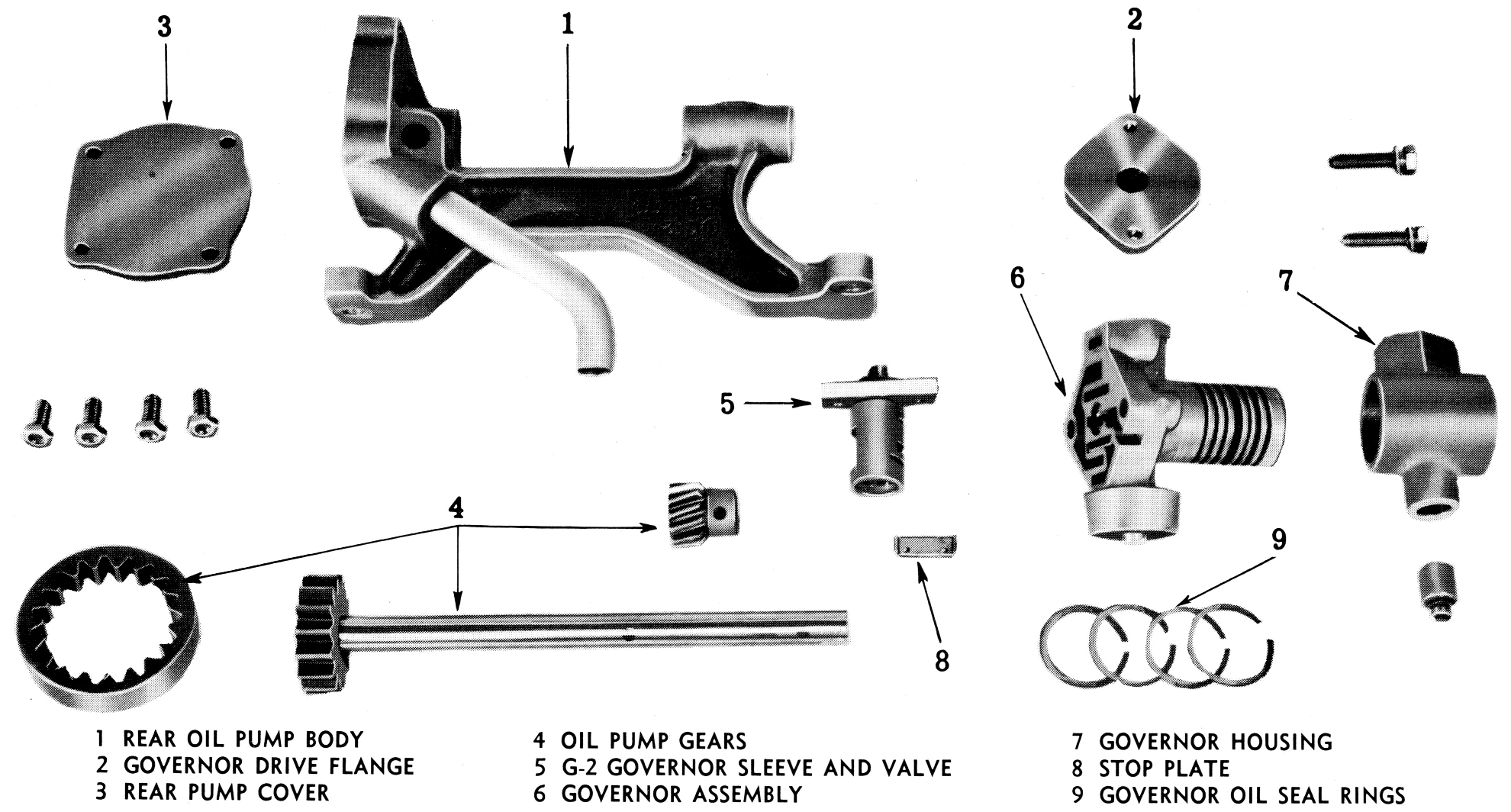
Step two is to add a centrifugal governor, driven by the output shaft. On early transmissions with a rear oil pump, the governor is typically part of the rear pump assembly. The governor rotates any time the drive wheels are turning, so its weights move outward in response to increasing road speed. Unlike the centrifugal weights in early automatic or semiautomatic transmissions, the governor doesn’t directly operate any of the transmission’s clutches or brakes. Instead, the motion of its weights opens a governor valve. An early Hydra-Matic shop manual explained:
As the governor spins, centrifugal force so positions the governor valve that a port is opened and some of this oil [from the pump] is admitted to the valve itself in such a way that pressure is built up to oppose the centrifugal force acting on the valve. This results in a governor pressure which increases with car speed.
This governor pressure is what’s called a “modulated” pressure: It’s proportional to the speed of the drive wheels, and may be less than or equal to line pressure, depending on how fast the vehicle is going (and thus how far the governor valve is open). In this way, the governor produces a hydraulic “signal” that indicates the vehicle’s road speed.
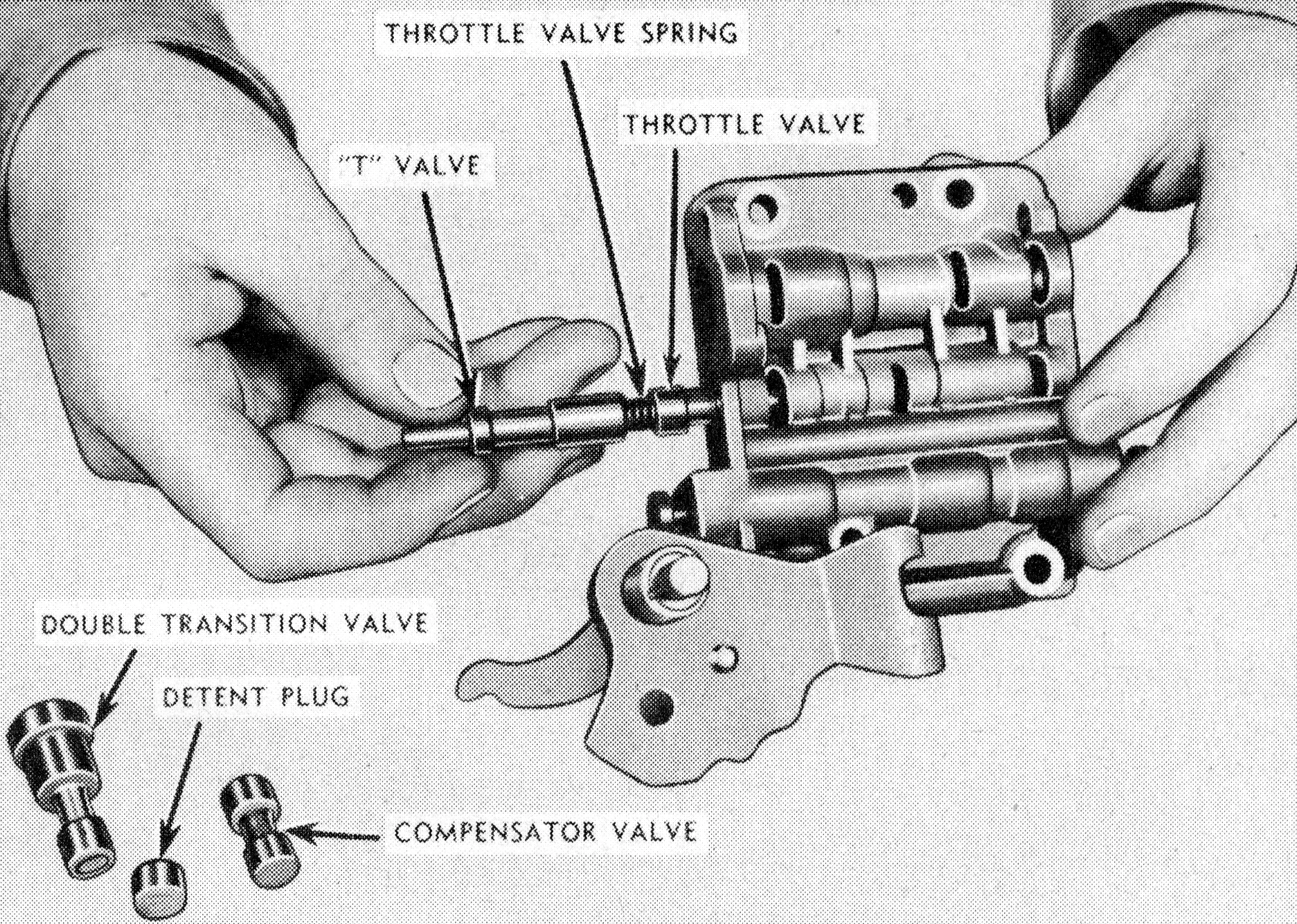
Step three is to create another signal that indicates loads, or torque demand. Generally, if the driver needs more torque for a given situation, they will press harder on the accelerator. So, the engineers who designed Hydra-Matic added a hydraulic throttle valve, controlled by the motion of the throttle linkage. The farther down the driver presses the accelerator, the wider the throttle valve opens, creating a modulated pressure (again less than or equal to line pressure) that’s proportional to throttle opening, and thus torque demand.
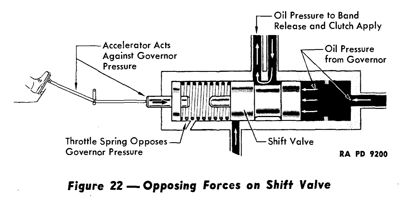
So, we now have two modulated pressure signals: governor pressure, which measures road speed, and throttle valve (TV) pressure, which measures load or torque demand. Next, the transmission needs to use those pressures to execute automatic gear changes.
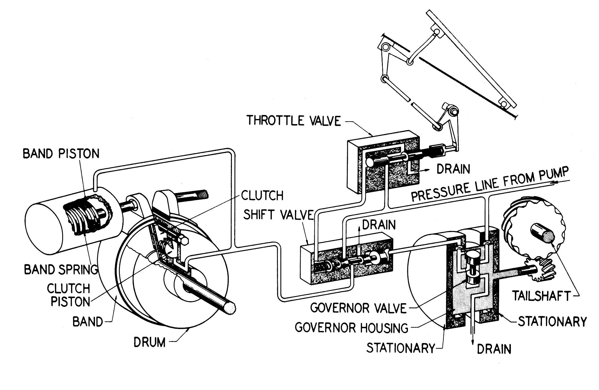
In these transmissions, each gear change is controlled by a shift valve that admits or cuts off line pressure to the different mechanical elements. Each automatic shift valve is spring-loaded; the spring force holds the valve in the downshift position. Governor pressure is applied to lands on one end of the shift valve, acting in the upshift direction, against the spring force. Throttle valve pressure is applied to the opposite end of the shift valve, acting in the same direction as the spring force. For the transmission to automatically shift up to a higher gear, the force applied by governor pressure (which, as I mentioned, is proportional to road speed) has to be great enough to overcome the spring force and the opposing throttle pressure, pushing the automatic shift valve to its upshift position.
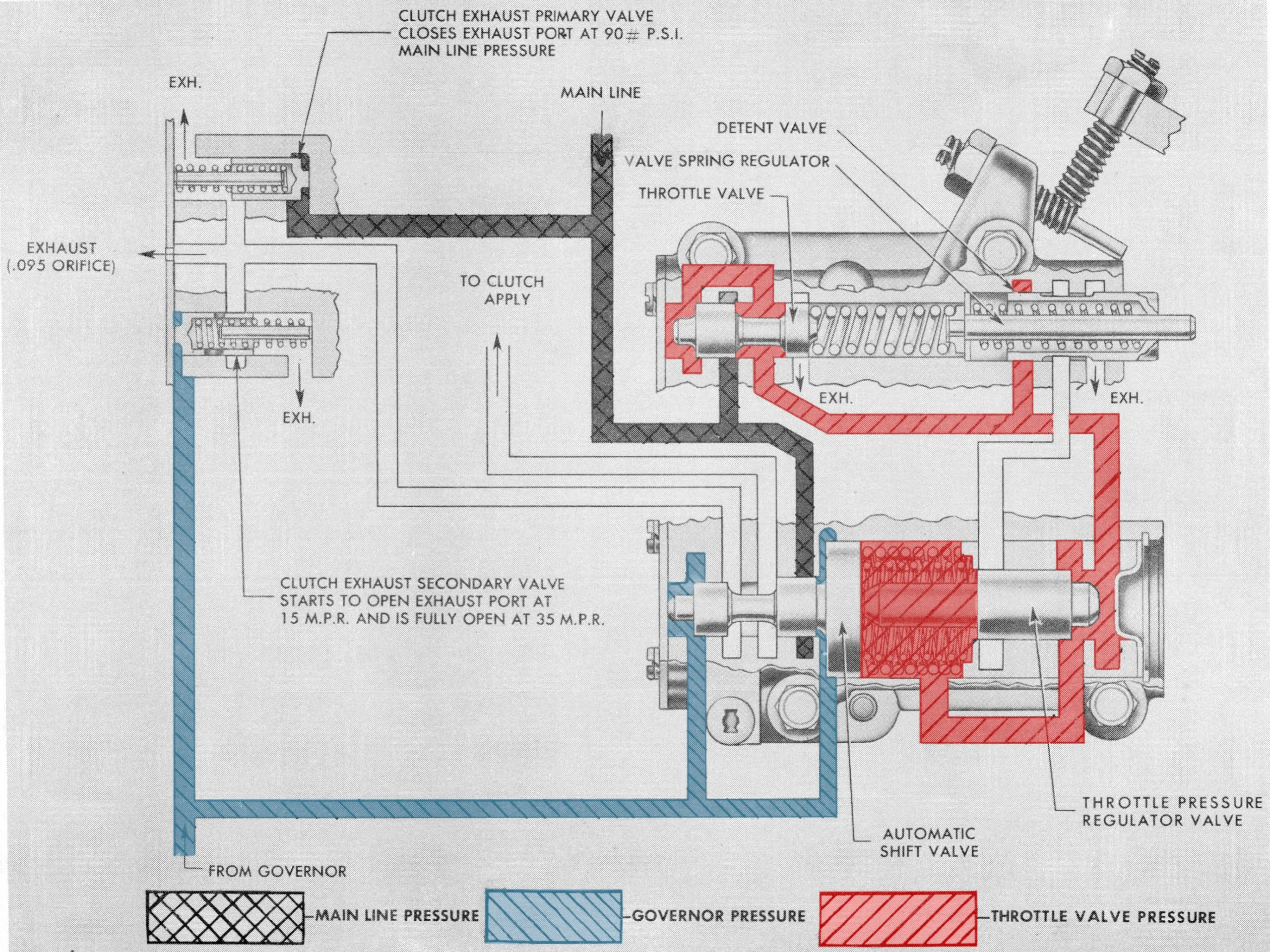
If you look closely at the color-keyed illustration above, you’ll notice that the governor pressure acts on the left side of the automatic shift valve in two different places. This is a small but very important point, because it means that even if the governor pressure and TV pressure are both at their maximum values (full line pressure on both sides), the total force the governor pressure exerts on the shift valve will be greater, and the governor will always eventually “win,” triggering an upshift. However, greater throttle pressure will delay the upshift, and can sometimes trigger a downshift if the transmission has already shifted to the higher gear.
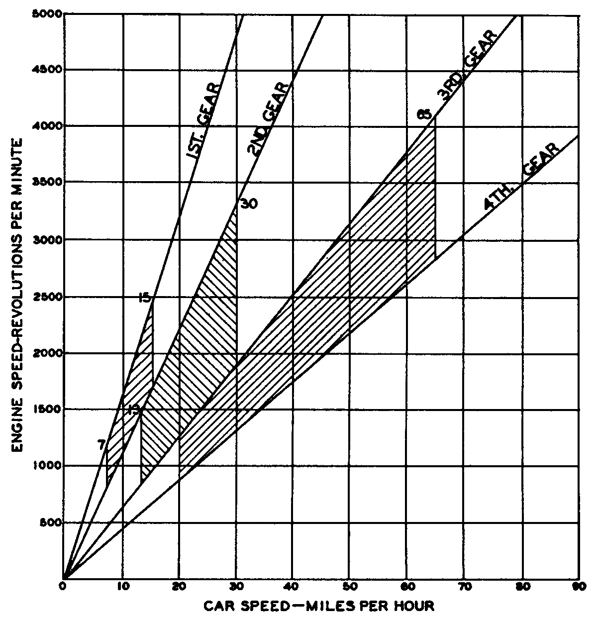
This system is essentially a simple analog computer. Each automatic shift valve is what computer engineers call a logic gate, producing a binary result (upshift/downshift) based on multiple input values. In practical terms, it means that shift points are not fixed, but are determined dynamically based on speed and torque demand. A shift between two gear ratios may take place anywhere within a range of road speeds, depending on the position of the accelerator pedal. That speed range can be raised or lowered by using a softer or stiffer shift valve spring.
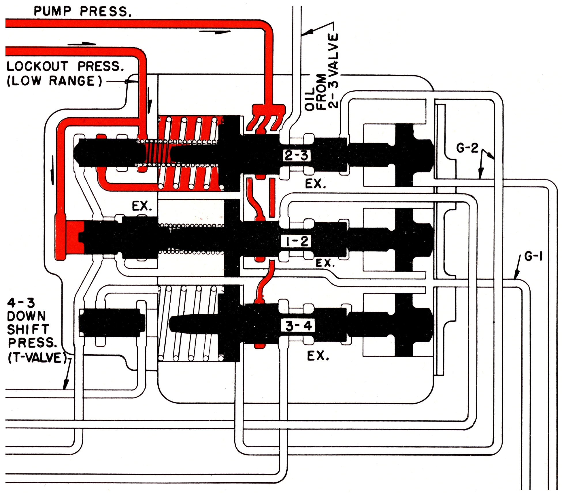
Each automatic shift valve normally only controls a single gear change, but if the transmission has three, four, or more speeds, they can be controlled by adding more shift valves after the first one, controlled in the same way. For example, an early 4-speed Hydra-Matic has three shift valves (1–2, 2–3, and 3–4). The spring forces for each valve are different, so they don’t all open at the same time.
Tweaks and Tricks
This opposing-forces strategy is complicated, and early critics like Oscar Banker insisted that it was much TOO complicated, with its array of hydraulic lines, linkages, and control valves. The designers of Hydra-Matic argued otherwise. Said GM engineers Oliver K. Kelley and Maurice S. Rosenberger in a 1947 SAE paper:
When the governor has to make its message felt in as many places as a 4-speed transmission requires, the simplest mechanism seems to be the hydraulic. It is a lot easier to diecast channels and drill holes to lead oil pressure around than to try to accomplish the same function with such things as flyballs, bellcranks, thrust bearings, and springs and rods.
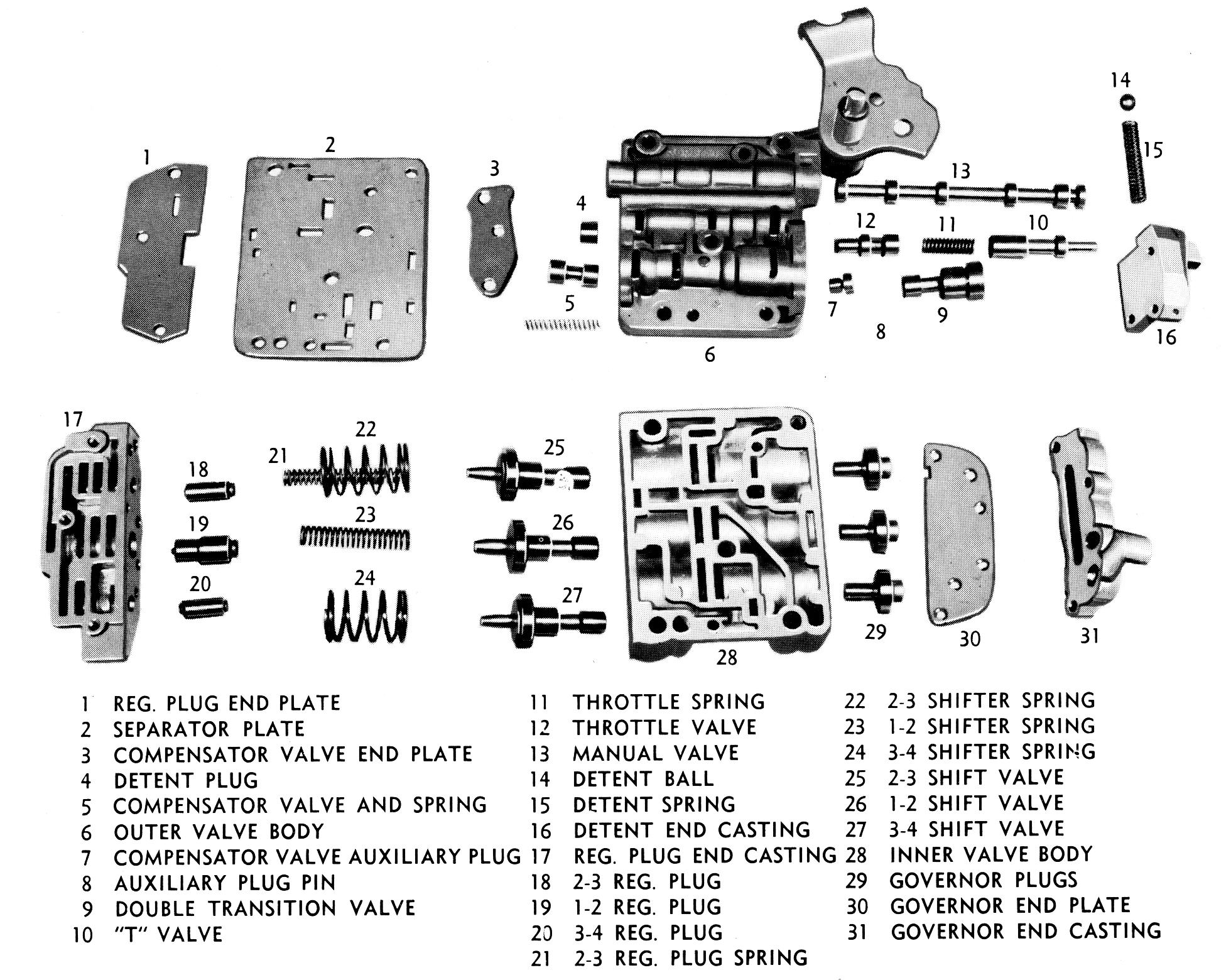
Greater complexity also allows greater versatility. Even the earliest production Hydra-Matic transmissions added various tweaks to the basic concept, like the following:
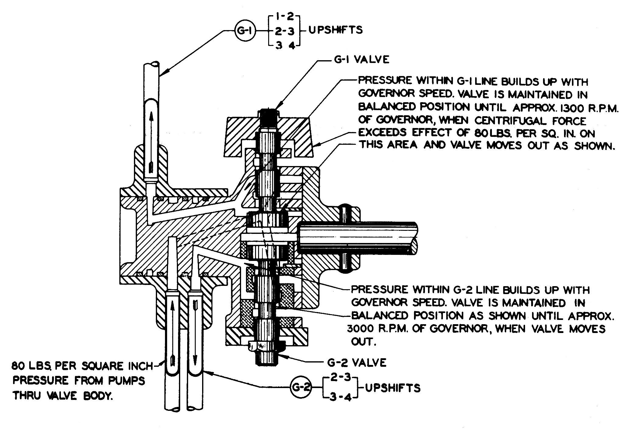
Hydra-Matic transmissions (and many other automatics with more than two speeds) actually have TWO governor valves rather than just one. Kelley and Rosenberger explained:
Let us say that it [the governor] will reach its maximum value at 70 mph. At this speed the governor delivers full line pressure, 80 psi. For practical reasons of leak control, this is the maximum pressure we decided to use in the transmission. The lowest speed function the governor has to perform is at approximately 3½ mph at zero throttle, as when coasting to a stop, when it has to return the transmission to low gear. The ratio of car speeds, and governor speeds, of these two points is 20 to 1. The ratio of pressures delivered by the governor would be 400 to 1. If the top pressure is only 80 psi, the lower pressure would be 0.2 psi. This would mean dealing with pressures and forces and return springs which are much too light for any satisfactory valve operation.
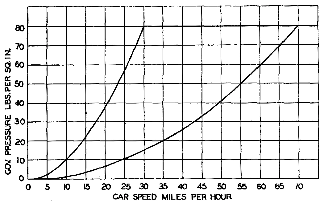
They continued:
For this reason, there is a low-speed governor and a high-speed governor. The low-speed governor carries a heavier weight and produces a pressure curve which rises much faster, reaching its top value at 30 mph so it has more than a full pound per square inch left at the final downshift point. This seems to be about the minimum satisfactory control force to use. If a hydraulic governor could produce a linear, rather than a square curve when plotted against speed, a single governor would be satisfactory. After a long search for such a governor we gave up and decided on two square-curve governors mounted in one rotating diecast body.
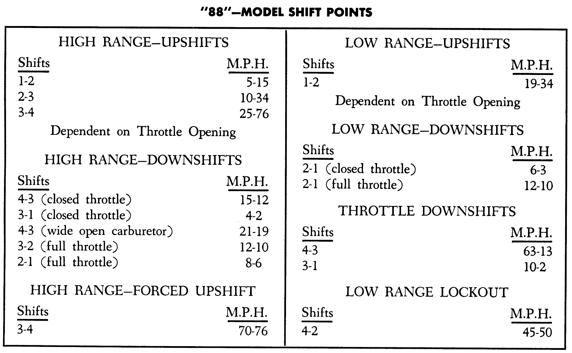
With transmission controls like this, it also became clear early on that there needed to be a significant difference between the speed at which the transmission would automatically upshift at a given throttle position and the speed at which it would automatically downshift, in order to prevent annoying “hunting” between gears. The early Hydra-Matic does this by using the flow of oil through the open shift valve to help hold the valve in the upshift position. Kelley and Rosenberger explained it like this:
At a given car speed, the governor pressure will exceed the existing downshift forces of the accelerator pressure and the spring and start moving the [shift] valve into upshifted position. When the valve has moved far enough to start opening the hydraulic supply port, a snap-over action takes place and the valve quickly completes its stroke. This snap-over action comes from the fact that in the upshifted position the hydraulic pressure delivered by the valve into the clutch also reacts on an annular area of the valve adding a new hydraulic force that helps the upshift. Obviously this new force gives hysteresis to the valve operation, meaning that if the throttle position is maintained constant and thus the downshift force is retained constant, the new hydraulic force staying in the picture at full 80 psi line pressure on the side of the governor force permits the governor to weaken a corresponding amount before the forces are once again in balance and the downshift starts. At the instant the valve has downshifted just far enough to begin to shut off the supply port and open the exhaust port, this hysteresis force dies, and the valve has a snap-over action in the downshift direction.
The practical effect of this was that the transmission will automatically downshift between gears at lower speeds than it will upshift between the same speeds.
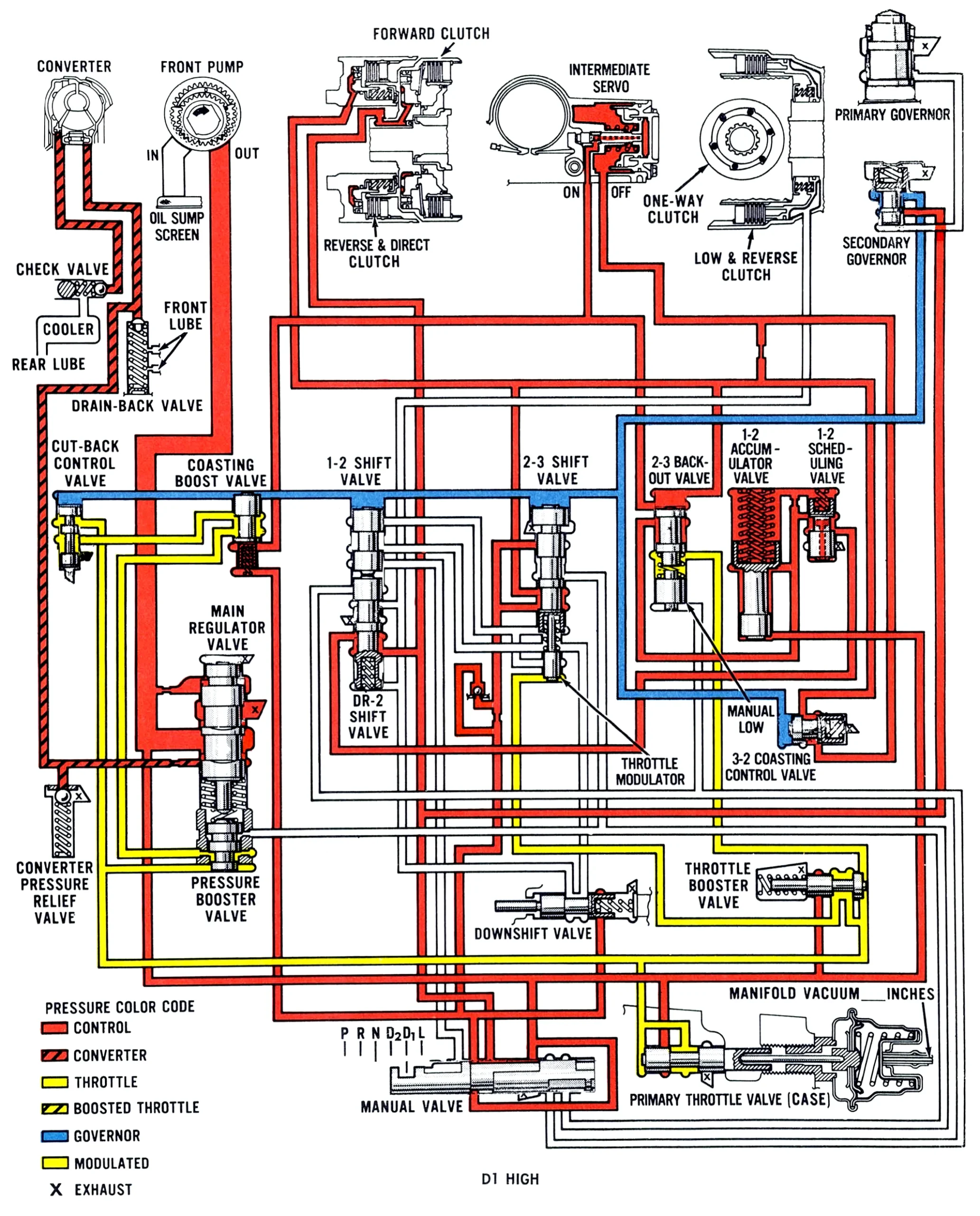
Some later automatic transmissions have traded throttle-controlled valves for vacuum modulators, which have valves that produce modulated pressure based on intake manifold vacuum or manifold absolute pressure rather than the physical movement of the throttle linkage. The purpose is the same as the throttle valve — to create a hydraulic signal based on load or torque demand — but it’s achieved a little differently. (There are pros and cons to each method, which are too complicated for this post.)
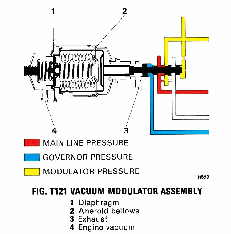
A lot of automatic transmissions have also used the throttle valve or vacuum modulator to vary the oil pressure that’s actually applied to engage the brakes and clutches, giving gentler shifts when torque demand is low and firmer shifts when the driver is really mashing the accelerator. GM TH400 and most TH350 transmissions use the vacuum modulator (pictured above) to combine governor pressure and torque demand (based on intake manifold absolute pressure) into a single modulated pressure that determines both shift points and shift smoothness. (In those transmissions, modulator pressure still opposes spring force to open or close the shift valves.)
Electronic Controls
Even if they have no electronic components whatsoever, opposing-forces hydraulic shift controls are really a form of analog computer. The earliest electronically controlled transmissions, first introduced in production by Renault in the late 1960s and Toyota in the early 1970s, were also analog computers, but their shift inputs used electrical signals from electronic sensors rather than hydraulic signals from modulating valves.
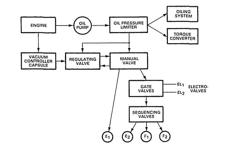
Actual shifts were still executed hydraulically, but the shift valves (which Renault called “electrovalves”) were opened electromagnetically rather than through oil pressure. The logic was really no different than the earliest Hydra-Matic, it was just executed using different tools.
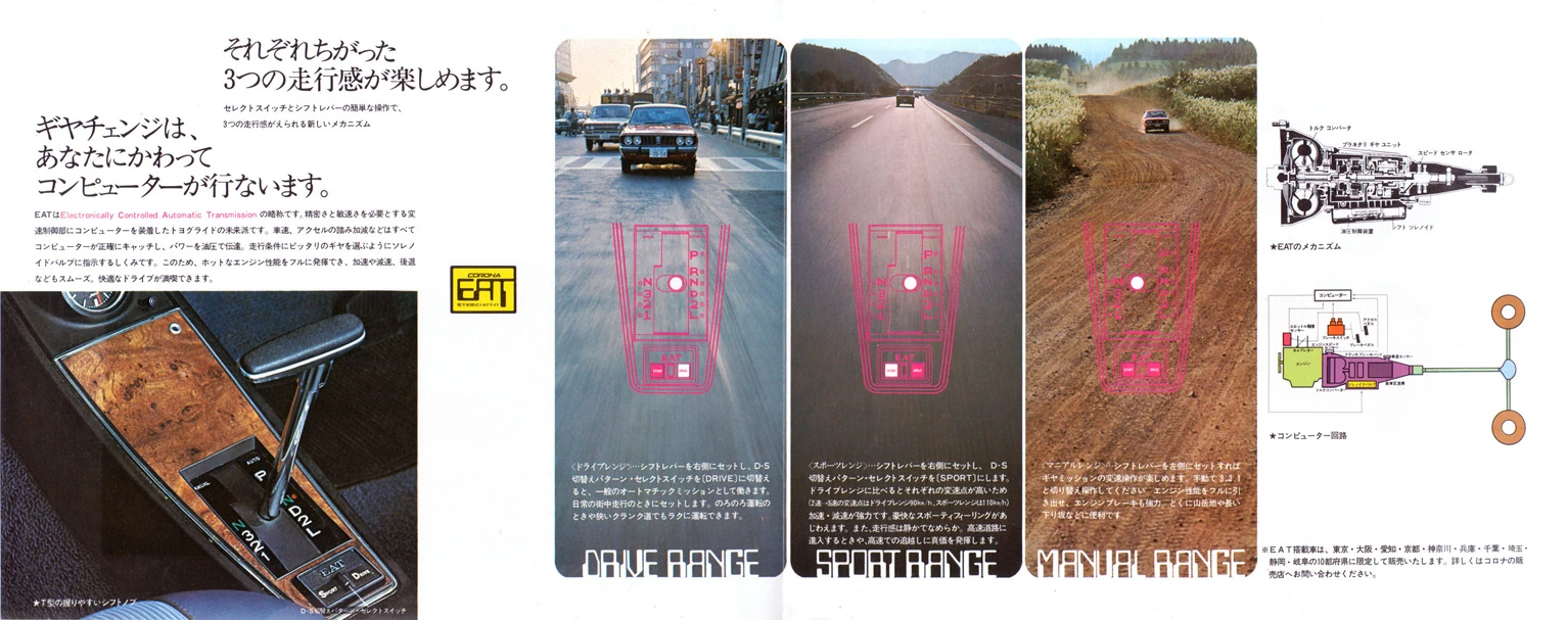
Electronic controls can be lighter and more compact than mechanical or hydraulic ones, and they eventually became more reliable, but the biggest advantage of electronic controls, especially with digital electronics, is that they can more easily integrate a wider range of input values. For instance, a digital transmission control computer can set shift points based on engine speed, road speed, accelerator position, engine coolant temperature, and transmission oil temperature — enabling it to do things like keeping the transmission in the lower gears for longer during warm-up or in strenuous conditions. Some later transmissions can even read lateral acceleration from a chassis accelerometer, to reduce the tendency to shift at inopportune times while cornering.
However, the kind of analog hydraulic controls Hydra-Matic introduced back in 1940 was the essential starting point for all those later developments. By modern standards, even a well-tuned early Hydra-Matic shifts in a series of graceless lunges, lurches, and thumps, but its controls cover all the basics, and they offered a workable template upon which to build. Their sheer complexity also offered numerous areas that could be tweaked and refined to make later transmissions work smoother and smarter, while simpler, cheaper, more seemingly elegant solutions either didn’t work at all or rapidly became obsolete, remembered now only by a handful of historians and trivia buffs.
Related Reading
The World’s First Automatic Transmission – The 1904-1907 Sturtevant Automatic Automobile (by me)
Planetary (Not Interstellar) Overdrive (1934-72) (by Paul N)
Early Hydra-Matic Users: Many Non-GM Automakers Bought This Pioneering Automatic Transmission (by me)
Hydra-Matic History: GM’s First Automatic Transmission (at Ate Up With Motor)









I find these these pieces on the arcania of early automatic transmissions fascinating. Thanks for this.
There are certain things that required special brains to design. The Bendix kickback “Automatic” bicycle hub. The windup clock. The thermocouple in your hot water heater. And the automatic transmission.
Even the simplest automatic transmission has seemingly endless contingencies for speed and load designed into its valve body.